Difference between revisions of "Max The Megapod Assembly Instructions"
Vorpalwiki (talk | contribs) (→GAMEPAD: Screw Sizes) |
Vorpalwiki (talk | contribs) (→Batteries (not included in kit)) |
||
| (174 intermediate revisions by the same user not shown) | |||
| Line 1: | Line 1: | ||
| − | + | ||
| − | |||
| − | |||
<!-- | <!-- | ||
==VIDEO BUILD INSTRUCTIONS== | ==VIDEO BUILD INSTRUCTIONS== | ||
| − | + | We currently have a build video for the gamepad (which is identical to our original hexapod gamepad), check back later for the robot build video. | |
| − | |||
| Line 15: | Line 12: | ||
===Hexapod Build Video Tutorial=== | ===Hexapod Build Video Tutorial=== | ||
| − | + | Check back in late October. | |
| − | |||
| − | |||
--> | --> | ||
| − | ==BILL OF MATERIALS (BOM) FOR | + | ==BILL OF MATERIALS (BOM) FOR MAX THE MEGAPOD== |
| − | ===Notes on Sourcing Parts=== | + | ===Notes on Sourcing Parts Yourself=== |
* These instructions assume you have purchased a kit from us. If you are sourcing your own parts, please be aware of the following additional information: | * These instructions assume you have purchased a kit from us. If you are sourcing your own parts, please be aware of the following additional information: | ||
| − | **If you are sourcing your own parts, you need to build the | + | **If you are sourcing your own parts, you need to build the power distribution connector assembly. For diagrams see [[Max The Megapod Battery/Switch Construction]]. This will take about 2 hours of soldering work. |
**Also see important information on that page if you are sourcing your own BEC. | **Also see important information on that page if you are sourcing your own BEC. | ||
| − | **If you are sourcing your own Bluetooth modules, please be aware that you will need to configure them to auto-pair and to have a UART speed of 38400 BAUD. Every module brand is a bit different so it's not possible for us to give you universal instructions on how to program them. We assume that if you source your own parts you are familiar with how to configure Bluetooth modules using AT-commands. | + | **If you are sourcing your own Bluetooth modules, please be aware that you will need to configure them to auto-pair and to have a UART speed of 38400 BAUD. Every module brand's firmware is a bit different so it's not possible for us to give you universal instructions on how to program them. We assume that if you source your own parts you are familiar with how to configure Bluetooth modules using AT-commands. (You can find tutorials online or videos on youtube, but like we said, different modules may not exactly match instructions you will find so be prepared to fiddle around a bit). Please do not ask our customer support for help on this topic. We sell pre-configured modules that auto-pair on boot for a very reasonable price. |
| − | * Full kits of parts as well as individual parts are available on [http://store. | + | **If you are sourcing your own Arduino Nano modules, you will need to flash the robot and gamepad code on them. You can find the code at the [https://github.com/vorpalrobotics/VorpalHexapod Vorpal Hexapod Repo on Github]. Note: there is no difference in software between the large and small versions of the hexapod. |
| + | * Please be very careful about substitutions. You might think you can substitute cheaper parts for the ones specified here. Don't bet on it. Walking robots are extremely difficult to design and we've chosen each part for a good reason. For example, if you try to substitute cheaper servos you are very likely to find that they don't provide enough torque for the robot to stand up, or they wear out within minutes due to being overstressed. If you substitute a different battery voltage, you'll either fry the servos or they won't have enough torque. It took 1000 hours of work to design the smaller hexapod on which this one is based, then another 500 hours to get the big version working well. | ||
| + | * Full kits of parts as well as individual parts are available on [http://vorpal-robotics-store.myshopify.com The Vorpal Robotics Store]. If you are new to Arduino and robotics we strongly recommend you purchase a kit instead of trying to self-source parts. The kits cut 3 to 4 hours off the build time, bringing it to typically 2 to 2.5 hours. The kits have all soldering done, programs are already loaded on the Nanos, Bluetooth modules are properly configured, and you know you have all the right parts to work together. About half the people who self-source parts end up buying parts that are incorrect or are so cheap that they will quickly fail (and they end up spending more money and far more time than if they had simply bought a kit to start with!) | ||
=== ROBOT BOM === | === ROBOT BOM === | ||
[[File:Choking-Hazard-Image.jpg|right|350px]] | [[File:Choking-Hazard-Image.jpg|right|350px]] | ||
| − | + | [[File:PinchPoint-Warning.JPG|right|350px]] | |
* ''Electronics:'' | * ''Electronics:'' | ||
** Passive Piezo Buzzer module and 3 wire cable (see image) [[File:Passive-Piezo-Buzzer-Module.jpg|right|thumb|Passive Piezo Buzzer Module]] | ** Passive Piezo Buzzer module and 3 wire cable (see image) [[File:Passive-Piezo-Buzzer-Module.jpg|right|thumb|Passive Piezo Buzzer Module]] | ||
** Arduino Nano, 5V, 16 mHz, ATMEGA328 or similar (marked RM in our kit to indicate it is pre-loaded with megapod robot software) | ** Arduino Nano, 5V, 16 mHz, ATMEGA328 or similar (marked RM in our kit to indicate it is pre-loaded with megapod robot software) | ||
| − | ** Rotary potentiometer, 10K Ohms, 6mm shaft diameter, with 3 wires pre-soldered. Also, matching dial cap and nut. | + | ** Rotary potentiometer, 10K Ohms, 6mm shaft diameter, with 3 wires pre-soldered. Also, matching dial cap and nut. If you are self-sourcing see our instructions: [[Max The Megapod Battery/Switch Construction]] |
** 1 x HC05 BlueTooth Module with 4 x F-F jumper wires for making connections (Note: the HC05 has six pins but only four are used in this project. Also, this is in the Gamepad Parts bag if you purchase our kit.) | ** 1 x HC05 BlueTooth Module with 4 x F-F jumper wires for making connections (Note: the HC05 has six pins but only four are used in this project. Also, this is in the Gamepad Parts bag if you purchase our kit.) | ||
** 1 x Servo Controller module (Adafruit 16-channel 12-bit I2C PWM/Servo driver or Adafruit clone) with F-F jumper wires for making connections, plus 1 two-pin shunt tying V+ to VCC | ** 1 x Servo Controller module (Adafruit 16-channel 12-bit I2C PWM/Servo driver or Adafruit clone) with F-F jumper wires for making connections, plus 1 two-pin shunt tying V+ to VCC | ||
| − | ** 12 x | + | ** 12 x MG958 servo motors and associated servo horns (you will only use the single-arm horn). NOTE: our kits come with one extra servo as a spare, there are 13 in the kit but only 12 are needed. We recommend 25T size metal horns for the knee servos (the ones that insert into the legs). We provide six metal horns with our kits as of November 2019. The plastic horns will wear out on the knee servos after about 4 to 8 hours of use and their splines will strip. |
| − | ** 1 x Power distribution wiring with on/off switch, Fuse, Tamiya battery connector, 3A 5V BEC, and servo extension connectors. If you are self-sourcing see our [[Max The Megapod Battery/Switch Construction|Circuit Diagrams]]. | + | ** 1 x Power distribution wiring harness with DPST on/off switch, Fuse, Tamiya battery connector, 3A 5V BEC, and servo extension connectors. If you are self-sourcing see our wiring instructions: [[Max The Megapod Battery/Switch Construction|Circuit Diagrams]]. |
* ''3D Printed Parts:'' | * ''3D Printed Parts:'' | ||
** 3 Robot Base Parts and bottom plate to hold the parts together. | ** 3 Robot Base Parts and bottom plate to hold the parts together. | ||
| + | ** 3 Robot Base Covers (used to enclose wiring inside the Base). | ||
** 4 Cap parts which screw together to form the cap of the robot. | ** 4 Cap parts which screw together to form the cap of the robot. | ||
** 6 x Legs | ** 6 x Legs | ||
| − | ** 12 x Leg Hinge halves | + | ** 12 x Servo Stops. These parts hold the servos in their compartments both in the base and the legs. |
| + | ** 12 x Leg Hinge halves with Leg Hinge Rings. The rings stop layer separation issues under stress. | ||
** 1 x Electronics Caddy to hold nano and servo controller | ** 1 x Electronics Caddy to hold nano and servo controller | ||
** 2 x Eye/glasses Decoration | ** 2 x Eye/glasses Decoration | ||
| + | * Screws and Fasteners | ||
| + | ** 12 x button head screw, M3 x 12mm long with M3 toothed lock washers (for servo horns) | ||
| + | ** 6 x #6-32 x 7/8" socket head screws (to fasten together "bowl" of base and cap parts). | ||
| + | ** 3 x #6-32 x 5/8" socket head screws (to fasten top of cap onto cap bowl) | ||
| + | ** 12 x #6-32 x 1.5" socket head cap screws for securing servos in their sockets. | ||
| + | ** 2 x #6-32 1” socket head screw (for accessory port) | ||
| + | ** 2 x #6-32 0.75" socket head screw (for accessory port) | ||
| + | ** 2 x #6 wingnut (for accessory port) | ||
| + | ** 19 x #6 nut | ||
| + | ** 19 x #6 toothed lock washer | ||
| + | ** 9 x #6-32 7/8” socket head screws with lock washers (for fastening Base and Cap sections together) | ||
* ''Miscellaneous:'' | * ''Miscellaneous:'' | ||
| − | ** 8 x | + | ** 12 x 608 Skate Bearings |
| − | ** | + | ** 8 x 18mm diameter ceramic magnet, approximately 5mm thick, north pole marked. 6 are for robot top, 2 for eye/glasses decorations |
| − | ** | + | ** 1 x T handle hex driver, 2mm, for button head screws. |
| − | ** | + | ** 1 x T handle hex driver, 7/64" for socket head screws. |
| + | * Tools not included in the kit: | ||
| + | ** Needle nose pliers are useful for holding the nuts while assembling BASE and CAP parts. | ||
| + | ** Slip-pliers are useful for forcing skate bearings into their press-fit locations on the Leg Hinges | ||
| + | ** Hot glue gun and glue sticks for securing magnets. You can also use cyanoacrylate glue (i.e. "super glue") or any glue that works on both plastic and metal. | ||
| + | ** If you have an electric screwdriver this will make assembly of the servo stops much faster. You would need a 7/64" hex key attachment. | ||
| + | === Batteries (not included in kit)=== | ||
| + | Three batteries are needed for this project: | ||
| + | * Max uses a main battery pack consisting of a five-cell NIMH battery pack with a nominal voltage of 6.0 volts, a minimum of 4000 mAh capacity, 18 gauge or thicker wires, and a full size male Tamiya connector. | ||
| + | * Max also uses a secondary 9v battery through a 5V regulator to drive the electronics (Arduino, Bluetooth module, Servo driver, etc). | ||
| + | * A second 9v battery is needed for the gamepad. | ||
| + | |||
| + | We recommend rechargeable 9v batteries, they can be NIMN, LI-ON, or NICAD. | ||
| + | |||
| + | Make sure you have a compatible charger for all rechargeable batteries. | ||
| + | |||
| + | A main battery pack we have used with success is this one: [https://www.amazon.com/gp/product/B003WTSPHG/ref=ppx_yo_dt_b_search_asin_title?ie=UTF8&psc=1 Dynamite 6.0v 5100 mAh NIMH Battery] although many others are available on the market. NOTE: we do not recommend going beyond 7500 mAh capacity as the weight of the battery will start to be too large past that point. | ||
| + | |||
| + | The battery specs should confirm that the main pack can output 5 amps continuously and can handle spikes to 10amps on an intermittent basis (5 seconds maximum). Most NIMH batteries at 4000 mAh or more will fulfill this requirement. | ||
| + | |||
| + | Note: we do not recommend substituting LI-ON batteries for the main pack on the Megapod, as they often cannot supply enough amps or will overheat under too high a load. We do not recommend NICAD batteries for environmental reasons. NIMH is really the perfect battery type for this application. | ||
| + | |||
| + | Many hobby and RC suppliers have cable converters to go from Tamiya connectors to other types (cross, XT60, etc.) so it is possible to use NIMH batteries with other kinds of connector if you can locate or construct a suitable adapter cable. If you construct your own battery conversion cable you must be extremely careful to do it properly, as batteries can be dangerous if connected improperly. | ||
| + | |||
| + | === GAMEPAD === | ||
| + | The gamepad for Max The Megapod is identical to the gamepad for Vorpal The Hexapod. See instructions for the gamepad here: [[Vorpal_The_Hexapod_Building_Instructions#Building_the_Gamepadd|Vorpal The Hexapod Gamepad Assembly instructions]] | ||
| + | |||
| + | ==Printing the Plastic Parts== | ||
| − | + | This section assumes you have basic familiarity with 3D printing and 3D printing terminology. If not, you might want to reference online materials such as youtube videos or information from your 3D printer manufacturer before attempting this project. | |
| − | |||
| − | |||
| − | |||
| − | |||
| − | |||
| − | |||
| − | |||
| − | |||
| − | |||
| − | |||
| − | |||
| − | |||
| − | |||
| − | |||
| − | |||
| − | |||
| − | + | ===OBTAINING THE STL FILES=== | |
| − | === | + | We have posted the STL files our public dropbox folder: [http://tinyurl.com/VORPALFILES VORPAL FILES]. Go to the STL folder, then the GAMEPAD and MEGAPOD folders have the files you need. (The same gamepad is shared among all our hexapod projects). |
| − | |||
| − | |||
| − | |||
| − | |||
| − | |||
| − | + | Please post your builds to places like Thingiverse, pictures to FaceBook, Instagram, etc., and videos of your robot to YouTube! This will help us grow and continue having the resources creating cool new projects for our community. | |
| − | This project has been finely tuned to make it easy to 3D print. No supports are required for any of the parts. In some cases you may want to use brims or rafts to help parts adhere to the print surface | + | ===MINIMUM PRINTER REQUIREMENTS=== |
| + | *The bed size should be at least 200mm cube (about 8 inches cube). The largest parts are the megapod Base-1, Base-2, and Base-3 parts, so it is the limiting factor on bed size. | ||
| + | *A heated bed is strongly recommended, especially if you are printing in ABS. | ||
| + | *An enclosure is recommended, especially if printing in ABS. | ||
| + | ===AMOUNT OF PLASTIC FILAMENT=== | ||
| + | * About 2.5 kg of plastic are needed to print the entire robot and gamepad. This does not include accessories like Joust attachments, etc. | ||
| + | * The amount of plastic used does depend on plastic type and exact print settings though, so your mileage may vary. | ||
| + | ===RECOMMENDED PLASTICS=== | ||
| + | *ABS, PETG, and PLA all work well. However, because there are some very large parts, ABS may cause you some warping issues if you don't have a heated bed, enclosure, and a printer tuned well for large parts. PLA is generally easier and has fewer issues with corners peeling off the print bed. | ||
| + | *We use eSun PLA PRO for this project and for us it works very well. PLA PRO is a little more flexible and stronger than typical PLA. We have no problems with warping even on the largest parts. | ||
| + | *This project requires less flexibility than the smaller Vorpal The Hexapod project, so ABS is less required for this project. | ||
| + | ===PRINTING TIPS=== | ||
| + | This project has been finely tuned to make it easy to 3D print. No supports are required for any of the parts (there is a support built into the models for the CAP parts). In some cases you may want to use brims or rafts to help parts adhere to the print surface. | ||
| − | + | There is some significant bridging with some spans up to 30mm (1.2"). It is important to tune your printer and make sure it can handle the bridging before attempting the large parts. A little sagging is ok and a drip or two can be easily removed, but you need decent ability to bridge. There are bridge testing and calibration models posted on sites like Thingiverse that may help you tune your printer before trying the big parts. | |
| − | If you are | + | ====PRINT SETTINGS==== |
| + | We print using the following settings on a Lulzbot TAZ 6 with 0.5mm nozzle: | ||
| + | * 0.4 layer thickness (or whatever layer thickness is the largest that will work on your printer) | ||
| + | * 2mm walls (i.e. four perimeters for a 0.5mm nozzle) | ||
| + | * 1.6 mm top and bottom (i.e. four layers at 0.4mm layer height) | ||
| + | * 25% infill | ||
| + | * You can print with thinner layers if your printer does not support 0.4mm layers or if you want a more refined look, it will just take longer. If you have a large nozzle (0.8mm or more) you should be able to go with bigger layers and save a lot of print time. Please report your findings to us at support@vorpalrobotics.com so we can advise future Makers of this project. | ||
| + | ====BRIMS AND RAFTS==== | ||
| + | * Brims or rafts are recommended for the following hexapod parts: Base, Legs, Cap. This ensures proper bed retention to avoid warping. These parts have relatively little contact area with the print bed, or have certain sections with little contact. | ||
| + | *If you have a very well dialed-in printer and have no issues with warping or corners curling up during prints, you can try them without brims. We don't use brims on anything but we've printed thousands of parts and we keep our printers very well tuned all the time with weekly maintenance and adjustments. | ||
| + | *These parts are large so if you don't use brims and things don't work out you might kill half a roll of plastic ... so maybe just use brims, it only adds a few minutes of cleanup time. | ||
| + | * Brims/rafts are not recommended on any of the other parts. The other parts generally have enough bed surface contact that they will print fine without brims. Your mileage may vary however and it is recommended that you keep a close eye on the first few layers of the print to make sure everything is sticking properly. | ||
| + | * We personally prefer brims over rafts (such as available in Cura and Simplify3D) as they are easy to remove and leave a clean look. | ||
| + | ====POST PRINT==== | ||
| + | Other than removing brims/rafts and the occasional drip, there is not any special post-processing required after printing. Some of the big bridges might seem a little saggy but generally speaking there's enough tolerance that this won't cause an issue. The biggest bridges are mostly hidden inside the robot so they won't affect cosmetics. | ||
| − | + | ====PRO TIPS==== | |
| − | * | + | *Do routine maintenance on your printer before printing the big parts: lubricate rods and lead screws, check bed leveling, replace nozzle if worn, do a calibration print, clean your print surface, etc. A few minutes of preparation will help you nail these prints and make a project you can be very proud of! |
| − | + | *Print the large parts (Base, Cap) at the ''start'' of new spools. The last thing you want is to run out of filament 95% of the way through a big part. | |
| − | + | *Print the smallest parts (servo stops, hinge rings, gamepad drawer) near the end of a spool. | |
| − | + | *If you have a large format printer, it is tempting to kick off all three Base parts at once and let it run overnight. We would recommend against that--the chances of killing an entire spool of filament due to an overnight power hit or other failure is just not worth it. Take your time, do the big parts one by one. One or two during the day, one overnight. It will all get done soon enough. An extra couple of days won't matter in the long run. | |
| − | |||
| − | * | ||
| − | |||
| − | |||
| − | |||
| − | |||
| − | |||
| − | * | ||
| − | |||
| − | * | ||
| − | |||
| − | |||
| − | |||
| − | |||
| − | |||
| − | |||
| − | |||
| − | |||
== Building the Robot == | == Building the Robot == | ||
You will need the following tools: | You will need the following tools: | ||
| − | * 2mm hex key. A 5/64 inch hex key will also work. This is in the | + | *Included in the kit: |
| − | * A marker that can write on dark plastic and still be seen, such as Sharpie Metallic or Sharpie Oil markers (white and yellow work great). | + | ** 2mm hex key. A 5/64 inch hex key will also work. This is in the Megapod Parts bag. |
| − | ** | + | ** 7/64 hex key at least 6" long (150mm). It needs to be long enough to reach screws through access holes in the Base and Cap. This is in the Megapod Parts Bag. |
| − | ** | + | *Not included in the kit: |
| + | ** Optional: A marker that can write on dark plastic and still be seen, such as Sharpie Metallic or Sharpie Oil markers (white and yellow work great on dark colored plastic, black or blue work well on light colored plastic). This can be used to make raised lettering on the robot and gamepad more visible. | ||
| + | ** Optional: Needle nose pliers can be helpful for holding nuts in place while tightening screws. | ||
| + | ** Optional: Slip-joint pliers can be helpful for forcing the skate bearings into their press-fit locations on the Leg Hinges | ||
| + | ** Optional: An electric screwdriver with a 7/64" hex key attachment will greatly speed up the process of locking the servos in place using the servo stop parts. There are 12 long screws to insert. Do yourself a favor, electric screwdrivers are not expensive these days and are very handy. | ||
| + | |||
| + | ===IMPORTANT WARNING: POWERFUL SERVOS MAY INJURE YOU=== | ||
| + | The motors on Max the Megapod are very powerful compared to the smaller Vorpal the Hexapod project. It is possible for the leg motions to pinch fingers or even possibly break fingers or cause other injuries. When powering on the Megapod you must keep fingers clear of places where the legs/hips can come together. In case of electrical issues the legs may move unexpectedly. Turning the power off will release the motors. Never let small children play with the megapod or grab at it when it's walking or moving. | ||
| + | |||
| + | If the robot is moving in an out of control manner, use a pencil, book, or rod to hit the power switch, which is large and easy to turn off. | ||
| + | |||
| + | You must at all times take standard precautions that are typical with large robotic projects. | ||
| + | |||
| + | If you are building your own electrical system please do not skimp by skipping adding the fuse to the circuit. This project may draw significant amperage and fuse protection is required. | ||
| + | |||
===Step by Step Instructions=== | ===Step by Step Instructions=== | ||
| − | + | ====STEP 1: Insert accessory port screws in the chassis==== | |
| − | + | This is easier to do before the Base is assembled into a single part. | |
| + | * Insert 1" #6-32 socket head screws in the bottom two holes of the accessory port with the head of the screw inside the hexapod, then secure using lock washers and nuts outside. Repeat for the top two accessory holes with shorter 3/4" #6-32 socket head screws. Two wingnuts go on the two lower screws, these will be used to secure accessories such as the Jousting Lance. | ||
<gallery mode=packed> | <gallery mode=packed> | ||
| − | |||
File:Accessory-Port-Diagram-V2.JPG|The accessory port is considered the "front" of the robot. | File:Accessory-Port-Diagram-V2.JPG|The accessory port is considered the "front" of the robot. | ||
| − | File:Accessory-Port-Screws.JPG|Longer | + | File:Accessory-Port-Screws.JPG|Longer socket head screws go on the bottom. Do not overtighten the nuts. |
File:Wing-Nuts-Installed.JPG|After installing the nuts, put the wingnuts on the bottom screws. They'll be used later to secure accessories. | File:Wing-Nuts-Installed.JPG|After installing the nuts, put the wingnuts on the bottom screws. They'll be used later to secure accessories. | ||
</gallery> | </gallery> | ||
| − | + | ||
| − | * | + | ====STEP 2: Build the BASE==== |
| − | + | * STEP 1A: Take the three outer parts of the base (STL files: Base-1, Base-2, Base-3) and arrange them to form the "bowl" of the base. Make sure the servo numbers are in the right order as you move clockwise around the three parts! It's possible to assemble them in the wrong order if you don't check. | |
| − | + | * STEP 1B: There are matching screw holes positioned on little rectangular outcroppings on the inside of the top ring, these require screws to bind the three parts together. Use three 7/8 inch socket head screws, toothed lock washers, and nuts to secure them. There is an access hole in the rim of the robot to allow the hex key to turn the screw. You may need to hold the nut in place using needle-nose pliers. Repeat for all three sections. | |
| − | + | <gallery mode=packed heights=250> | |
| − | + | File:Base-Exploded-View.JPG|Line up the three main pieces of the base, ensuring the servo numbers are in order. | |
| − | + | File:Access-Hole-In-Base.jpg|Small access holes are strategically placed around the base so the hex key can turn the screws to secure the three base pieces. | |
| − | + | File:Securing-Base-Sections.jpg|Use the access hole in the Base parts to secure screws that bind the three base parts together. | |
| − | + | File:Megapod-Foam-Squares.jpg|Peel the backing off the foam squares that came with the kit and attach them to the bottom of the base. Stack them on top of each other. | |
| − | + | </gallery> | |
| − | + | * STEP 1C: Take the Base Bottom part and place it inside the base. There is a nub in one place that will only allow it to be inserted in one orientation. Use 5/8" screws in the outer ring of holes in the bottom to secure it to the base. The head of the screw should be on the outside of the robot and nuts should secure the screws on the inside. NOTE: There are six outer ring holes, however you only need three of them (one in each base section) to secure the robot. Early versions of the kit only had three 5/8" screws. | |
| − | + | * STEP 1D: Take the foam squares that came in your kit and stick them on the bottom of the robot. (Build up several layers, they stick to each other.) These foam pads will reduce the shock and stress on the robot when it goes down to the floor on certain dance moves. Without these pads, the robot leg servos and body structure may undergo too much stress. | |
| − | * | + | |
| − | + | ====STEP 3: Install the electrical system in the base==== | |
| − | + | * STEP 3A: Take the potentiometer and remove its dial cap, then unscrew the nut and set these items aside for now (don't lose them). Push the potentiometer shaft from the inside of the chassis into the hole that is surrounded by the markings "STOP", "TST", etc. The wires coming out of the potentiometer should be pointing down. The little metal nub sticking out of the potentiometer should match with a tiny rectangular hole that is near the marking "TST". Put the retaining nut on the potentiometer, hand tighten first and then give it just another half turn or so with pliers if desired. Turn the knob all the way counter-clockwise, then insert the knob so it points to the letter "O" in the word "STOP". | |
| − | + | * STEP 3B: Take the large DPST on/off switch (which is attached to the battery holder and power distribution assembly) and thread the switch wires from the inside through the gap at the bottom of the switch hole (see picture). Carefully push the wires one by one through the slot below the switch hole. Once all the wires are through, push the switch into the switch hole. It should be oriented with the "1" to the right. Press carefully into the hole, it should snap firmly in place. | |
| − | * | + | ** If the fit is too tight to get the switch in place, lightly sanding or filing the hole to make it a tiny bit larger should work. |
| − | + | <gallery mode=packed heights=200> | |
| − | + | File:Switch-Insert-1.jpg|Thread the switch and its wires through the Base, there is an opening under the switch hole. | |
| − | + | File:Switch-Insert-2.jpg|Bring the wires up through the small gap below the switch hole. Be careful with the large wires, they require some pressure or some flexing of the plastic to get through. | |
| − | + | File:Switch-Insert-3.jpg|All the wires are now coming through the switch hole. | |
| − | <gallery mode=packed> | + | File:Switch-Insert-4.jpg|Press the switch into the hole, it should snap into place. The "1" should be to the right. |
| − | File: | + | </gallery> |
| − | File: | + | |
| − | + | ====STEP 4: Insert servos in the chassis==== | |
| − | File: | + | * Next, insert the servo into the chassis as shown in the diagrams below. As you insert the servo into the chassis, slowly press it straight into place until it fully seats. Use a servo stopper and one 1.5 inch #6 socket screw to secure the servos in place. Use the hole nearest to the front of the servo. NOTE: There are two holes in the Servo Stop but we have found that one screw is enough to hold it. The second hole could be used if you find that the plastic you use tears through the hole. We have not seen this but we added the second hole just in case. |
| + | <gallery mode=packed heights=250> | ||
| + | File:Servo-in-Base-2.jpg|Insert each servo with the wire coming out away from the robot as shown here. Press in completely. | ||
| + | File:Servo-in-Base-3.jpg|Insert a servo stopper (shown in red) and secure with one 1.5" screw in the hole nearest the front (the servo shaft and horn is in the front). Thread the wire into the body of the robot through the hole as shown. | ||
| + | </gallery> | ||
| + | |||
| + | ====STEP 5: Insert the servos in the Legs==== | ||
| + | The technique is very similar to inserting the servo into the chassis. | ||
| + | *Insert the servo straight into the leg socket so that the wire is coming out of the servo facing away from the plastic leg and the face of the servo with the shaft and servo horn goes into the open faced side of the leg, as shown in the diagram. | ||
| + | *Secure the servo in place with a servo stopper and one 1.5 inch screw as you did with the hip servos in the base. NOTE: There are two holes in the stopper but we have found that one screw is enough to hold it. The second hole could be used if you find that the plastic you use tears through the hole. We have not seen this but we added the second hole just in case. | ||
| + | *The servos in the legs are called the "knee" servos. Each leg has a higher number on it, this is the knee number, they run from 6 to 11. Again, write this number on the black connector at the end of the servo wire. PRO TIP: For 6 and 9, underline the number so you don't read them upside down! | ||
| + | <gallery mode=packed heights=200> | ||
| + | File:Servo-Insert-Leg-v2.png|Insert Servos in Legs | ||
| + | File:Servo-Leg-Inserted-v2.png|Push until fully seated | ||
| + | File:Servo-Stopper-In-Leg.jpg|Use the servo stopper and two screws to lock the servo in place | ||
</gallery> | </gallery> | ||
| − | + | ||
| − | * | + | *Thread each leg servo wire into the bottom wire guide slot on the chassis. Each leg servo should be matched with a hip servo plus 6. The legs are marked with the hip number near the top and the knee number below that. For example, the leg marked 6 should be threaded through the wire guide on hip servo 0, leg 7 goes with hip 1, leg 8 goes with hip 2, etc. Add 6 to the hip number to get the leg number. |
| − | + | ||
| + | ====STEP 6: Plug in the Servos==== | ||
| + | Thread the servo wires into the chassis using the routing holes, as you did with the hip servos. The power distribution harness has marked servo extension sockets for each servo. Each hip servo is marked on the BASE showing its number. the knee servo for each hip is numbered six higher than its corresponding hip. For example, hip servo number 3 will be attached to knee servo number 9, because 3+6=9. | ||
| + | |||
| + | When plugging the servos in, make sure you match the light yellow servo wire to the white servo extension wire, and the dark brown servo wire should match with the black servo extension wire. | ||
| + | |||
| + | ====STEP 7: Make Robot Electrical Connections==== | ||
| + | |||
| + | Now use the diagram below in the electrical section to make the rest of the robot's electrical connections. You'll be using the Robot Arduino Nano (marked "R"), the Servo Driver, Bluetooth Module marked "S", the buzzer, and a bunch of jumper wires. Make sure you use the longer jumper wires for the SDA and SCL connections between the Nano and the Servo Driver. | ||
| + | |||
| + | ====STEP 8: Assemble the leg hinges==== | ||
[[File:Servo-Bracket-Alignment-v1.png|thumb|350px|right|Align the leg hinges as shown here. The bumps (see arrows) should both be near each other when properly aligned. Hold one in each hand with the ends of the U shape between thumb and forefinger.]] | [[File:Servo-Bracket-Alignment-v1.png|thumb|350px|right|Align the leg hinges as shown here. The bumps (see arrows) should both be near each other when properly aligned. Hold one in each hand with the ends of the U shape between thumb and forefinger.]] | ||
| − | + | Each leg hinge is composed of two identical U-shaped parts. Take one in each hand and align the two so that the bump (shown in the diagram at the right) are both near each other. Turn one 90 degrees with respect to the other. | |
| − | + | *Gently squeeze each piece between thumb and forefinger, which causes the little jaws in the center to open up slightly. Work the two halves together. Keep squeezing harder until the ends slide into place. NOTE: Make sure you printed version V1r2b or later. Earlier versions made it too difficult to squeeze the parts into place. If you printed an earlier version, you may need to trim some plastic using angle cutters to get the parts together. | |
| − | **At this stage, you may notice that the parts are loosely clamped on each other. Don't worry! When you place the leg hinges over a servo, the servo will spread it apart and they will lock together tightly. | + | *If you used PLA and are finding it hard to bend, briefly soaking the pieces in very hot tap water has been reported to make it easier. Take care not to scald yourself, the water does not have to be boiling, just hot from the tap. You only need to dip the ends that will lock over each other, not the parts you will squeeze. Use caution. |
| − | * | + | *At this stage, you may notice that the parts are loosely clamped on each other (this depends on plastic used and whether your printer over- or under-extrudes). Don't worry! When you place the leg hinges over a servo, the servo will spread it apart and they will lock together tightly. |
| − | + | *Insert a 608 skate bearing into the socket on one side of the leg hinges. Pliers may be necessary to press them into place. Make sure you clean up any drips inside the recessed area for the skate bearing before attempting to insert the bearings. | |
| − | * | + | |
| − | + | ====STEP 9: Attach Leg Hinges==== | |
| − | + | The leg hinges connect the hips to the knees. They only go on one way. If you made sure to align the bumps when assembling the leg hinges, this will result in correct orientation of all legs. | |
| + | *First place the end that matches the servo horn on about halfway. Make sure the servo horn slides under the little pocket at the end of recessed area that accepts the horn. | ||
| + | *Very slightly bend the U shaped piece while pulling the skate bearing side over the hemispherical bump on the other side of the servo holding area. It's a little easier to do the knees (servos mounted to legs) first, followed by the hips (servos on base). | ||
| + | *NOTE: It will be a tight fit, but it should not be excessively difficult to push the hinge over the hemispherical bearing. If you find you are struggling, that means the hinges are too tight. This may affect walking. This can be due to the kind of plastic you used or how your printer is adjusted. You may need to gently spread the two legs of the U shape by hand before putting the hinge on the robot. Be careful of course not to break the hinge. | ||
| + | *When completed, double check to make sure the servo horn went into the covered pocket at the end of its recessed area. This pocket keeps the horn from slipping out of the hinge during stressful operations. | ||
| + | |||
| + | ====STEP 10: Enclose the electronics modules in their caddies==== | ||
| + | <!-- | ||
{| class="wikitable" align=right style="float:right; background:transparent; margin: {{{margins|1em 1em 1em 1em}}}; {{{style|}}}" | {| class="wikitable" align=right style="float:right; background:transparent; margin: {{{margins|1em 1em 1em 1em}}}; {{{style|}}}" | ||
|- | |- | ||
| <youtube>5T7E1IqHxNc|Electronics Caddy Tutorial</youtube> | | <youtube>5T7E1IqHxNc|Electronics Caddy Tutorial</youtube> | ||
|} | |} | ||
| − | + | --> | |
| − | + | Now things look pretty messy with all those wires hanging loose, let's clean it up by stowing the Arduino Nano, Bluetooth module and Servo Driver in their caddies. The caddies will keep them safe by making sure they can't short out against each other or touch screws, etc. | |
| − | + | * '''STEP 10A: Insert Caddy Bars''' Insert the electronics caddy bars as shown in the diagrams below. Notice carefully how they are inserted. Don't insert them upside down, the little hump should be facing inward toward the caddy. You may need to slightly squeeze the forked section at the end to work it into the hole. Once inside, it may be difficult to remove because it will snap into place, so be sure you're putting it in the right way. | |
| − | <gallery mode=packed> | + | <gallery mode=packed heights=300> |
| − | File: | + | File:Insert-Caddy-Bar-1.jpg|Insertion of the caddy bar into the Nano caddy. Notice the orientation, don't put the bar in upside down. The same technique is used for the Servo Driver Caddy. |
| + | </gallery> | ||
| + | * '''STEP 10B: Insert the Arduino Nano into its caddy''' Carefully insert the Nano as shown, making sure you don't pull out any of the wires. You may need to wiggle the caddy bar from side to side a bit so that components can slide past it during insertion. Notice that the end of the Nano that has the USB port must go in last. | ||
| + | |||
| + | <gallery mode=packed heights=250> | ||
| + | File:Insert-Nano-In-Caddy-1.jpg|Insert the Nano in the orientation shown. | ||
| + | File:Insert-Nano-In-Caddy-2.jpg|You may need to wiggle it a bit or press on the bar to work it into place. | ||
| + | File:Insert-Nano-In-Caddy-3.jpg|Note how the USB port is accessible through the top after full insertion. | ||
</gallery> | </gallery> | ||
| − | + | ||
| − | <gallery mode=packed> | + | * '''STEP 10C: Insert the Servo Driver into its caddy''' Carefully insert the Servo Driver as shown, making sure you don't pull out any of the wires. You may need to wiggle the caddy bar from side to side a bit so that components can slide past it during insertion. Notice that the end of the Servo controller with wires sticking out of it must go in last. |
| − | File: | + | |
| − | File: | + | <gallery mode=packed heights=200> |
| − | File: | + | File:Insert-ServoDriver-In-Caddy-1.jpg|Insert the Servo Driver in the orientation shown. |
| + | File:Insert-ServoDriver-In-Caddy-2.jpg|You may need to wiggle it a bit or press on the bar to work it into place. | ||
| + | File:Insert-ServoDriver-In-Caddy-3.jpg|Note that the end with the wires goes in last. | ||
</gallery> | </gallery> | ||
| − | + | ||
| − | <gallery mode=packed> | + | * '''STEP 10D: Insert the HC05 Bluetooth Module''' The diagrams here do not show the wires to make them easier to visualize. The HC05 Bluetooth module with a name beginning with "S" should be used for the robot. For example, the label will read something like "VORP S2944" (the number will differ). The one marked "M" will be used for the gamepad. Slide the HC05 into the side drawer as shown. When inserting, be careful not to pull out the wires, which will be a little tight. Work the wires into the little space provided so they stay clear of the robot's cap when it gets screwed on later. |
| − | File: | + | |
| − | File: | + | <gallery mode=packed heights=250> |
| + | File:Insert-HC05-in-Caddy-1.jpg|Insert the HC05 into the side drawer of the Nano Caddy as shown. | ||
| + | File:Insert-HC05-in-Caddy-2.jpg|When fully inserted, the indicator light will still be visible through the small oval. | ||
| + | File:Insert-HC05-in-Caddy-3.jpg|The wires should be tucked into the little cavity near the pins of the HC05. | ||
</gallery> | </gallery> | ||
| − | |||
| − | |||
| − | |||
| − | |||
| − | |||
| − | == | + | ====STEP 11: Power up!==== |
| − | + | Make sure the on/off switch is off, and the knob is turned to STOP. Insert batteries and power on the robot using the on/off switch. You should hear a beep, a pause, then a second beep. The servos should all twitch into position. If the robot does not move at all, immediately turn the switch off and check your connections again. If some of the servos don't move then gently push them with power off to see if you can free them up. If they still won't move, try pushing them with power applied, but turn off the power within 30 seconds if they're locked up. If you can't get the servo to move it will need to be replaced. | |
| − | |||
| − | + | [[File:Servo-Horn-Orientation.png|thumb|right|The servo horn should come straight out from the body at a 90 degree angle as shown here. Do not turn the servo shaft by hand until after it has moved under power!]] | |
| − | [[File: | ||
| − | + | ====STEP 12: Insert Servo Horns==== | |
| + | The servo horns are all at random angles right now due to the servo pre-check. In this step we'll make them point in the right direction. The knee servos are not at 90 degrees when the knob is all the way counter clockwise, rather they are at a 30 degree standing angle. | ||
| − | + | We need to get them to 90 degrees so its easy to align the servo horn, and this is done by going into "Adjust Mode". Turn the knob very slightly clockwise until you hear a beep, then stop. After about one second you will see all the knee servos twitch. This is "adjust servo horn mode". All servos (knees and hips) are now at their halfway point, 90 degrees. | |
| − | |||
| − | |||
| − | + | Now you need to take each single arm servo horn and carefully insert it on the shaft so that it is sticking straight out as shown in the figure. You will not always be able to make the horn come totally straight out. This is because there are only 22 little groves (splines) in each shaft, meaning you can in general only come within about 8 degrees of being at a perfect 90 degree angle. This amount of error is acceptable for now, just get it as close as you can. Later we'll use Trim Mode to make fine adjustments. | |
| − | |||
| − | + | ====STEP 13: Test Knee Positions==== | |
| + | Turn the knob fully counter clockwise (to STOP) and the robot will go into "stand still" mode. Place it on a level surface such as a table top. Do all of the legs touch the ground? If one or more legs don't touch the ground, you need to adjust the servo horn on the knee a little bit so it does touch. Gently pull off the servo bracket. Pull the servo horn off, and put it back on just a little bit moved so the leg would move closer to the ground. Put the servo bracket back on, and see how it looks. Do this until all legs are at least slightly touching the ground. Again, you can't necessarily be perfect due to the 8 degree increments the servo horns can be moved. But you should be able to be close enough that all legs at least slightly touch the ground. | ||
| − | + | ====STEP 14: Insert Servo Screws==== | |
| + | Now that the legs are adjusted, you can insert the M3x12 screws (with M3 lock washers) into the servo horns to lock them in place. Note that you will NOT be using the screws that were in the little bag the servos came in, you'll be using the separate pack of screws, which are longer than the ones in the servo bag. Do not overtighten these screws, as you could possibly crack the servo brackets. Just turn the screws until you start to feel resistance, then turn a quarter turn more and stop. | ||
| − | * ''' STEP | + | ====STEP 14: Test the Servos==== |
| + | *'''STEP 14A: Using TST Mode''' | ||
| + | **To test whether every servo is working, put the robot on something that will lift its legs off the table top, but won't interfere with the legs (a small box, etc.). | ||
| + | **Start with the knob on STOP, then slowly turn it clockwise. You'll hear one beep (Adjust mode), then a second beep (Test mode). Stop turning and the robot will go into "individual servo test mode". In this mode, every hip servo will move, one by one. When all the hips have moved, every leg will move, one by one. You should see every servo move, in order. If some don't move, check your connections. A common error is to plug a servo connector into the servo controller backwards (i.e. the brown wire is matched with the yellow pin instead of the black pin). If the servos do not move in a sensible order, that probably means you plugged a couple of servos into the wrong sockets in the electrical harness. | ||
| − | * '''STEP | + | *'''STEP 14B: Test Using Demo Mode''' |
| + | **Ok, everything looks good, so time for a full test. Turn the knob to STOP, then put the robot on the floor, somewhere that has at least a few feet of room in each direction. (Caution: it's tempting to do this on a table top, but unless you have a huge table this is not advisable, Max will run pretty fast at some points during the demo.) | ||
| + | **Turn the knob to DEMO, and about one second later the robot will go through a series of movements to demonstrate some of the things it can do. The full demo only takes about 30 seconds, then repeats. Here, you are looking for the robot to, for example, be able to get back up off the floor after doing some of its dance moves. | ||
| + | **If the robot struggles to get off the floor, you may have a battery that is not fully charged, or there may be drips or other obstructions stopping some legs from moving fully. See the [[Vorpal Combat_Hexapod Troubleshooting Guide|Trouble Shooting Guide]] for more information about different kinds of issues that can occur. That guide was written for the small robot, but most of the things that can go wrong with Max the Megapod are identical to the things that can go wrong with Vorpal The Hexapod. | ||
| − | + | ====STEP 15: Store electronics and wires in the Base==== | |
| + | Carefully stow the caddies into the base, using any available convenient space. Arrange the servo and other wires so they don't cross any screw holes. The three Base Cover parts can be used to secure everything, however you may not want to put in more than one screw each at this point, until the robot is more fully tested. Be sure the two battery connectors come through the holes provided for them in the Cover parts. | ||
| + | <gallery mode=packed heights=250> | ||
| + | File:All-Electronics-Inserted-In-Base.jpg|Carefully stow the caddies into the base, being careful not to pull out any wires. Press servo wires into place too, make sure they don't overlap any screw holes. | ||
| + | File:Base-Covers-3.jpg|Place the three covers in place. It is not necessary to screw them down at this point, you may want to wait until the robot is more fully tested. We normally just put in one screw on each component at this point--this makes it easy to get back into the electronics if something needs to be checked. | ||
| + | </gallery> | ||
| − | * '''STEP | + | ====STEP 16: Assemble the Cap==== |
| + | *'''STEP 16A: Assemble the Four Cap Parts''' | ||
| + | **First assemble the three large pieces after removing the support coming out of the center. Be aware that there is a correct ordering to them, the two flaps that stick out near the bottom need to be opposite each other so the cap can slot into the Base and lock in place. Use 7/8" screws to secure the three parts together as shown. There are access holes around the rim that allow the hex key to reach the screws. Use nuts and locking washers to secure the screws. | ||
| + | **Secure the top of the cap onto the bottom three pieces using three 5/8" #6 socket screws and their associated nuts and toothed lock washers. | ||
| + | <gallery mode=packed heights=250> | ||
| + | File:Cap-Exploded.JPG|Arrangement of the four Cap parts. Note that this diagram shows the support in place, this should actually be removed prior to assembly. | ||
| + | File:CAP-Assembly-order.JPG|Make sure the two flaps at the rim are opposite each other when ordering the three main parts. | ||
| + | </gallery> | ||
| + | * '''STEP 16B: Put magnets in the Cap''' Insert a magnet in each magnet holder in the cap. The magnets are marked with a dot on the North pole side. It is important that this dot be showing after installation. In other words, insert the magnet with the non-dot side down. The magnet is about 2mm smaller in diameter than the hole, so you will need to use hot glue (or some other kind of glue that works on metal and plastic) to secure it. | ||
| + | * '''STEP 16C: Decorate''' If desired, use a permanent marker to color the Vorpal "V" on top of the Cap. Oil markers work well. On light colors of plastic a black permanent marker will also work. | ||
| + | * '''STEP 16D: Put Cap on the Hexapod''' | ||
| + | **Screw the cap on the robot by lining up the tabs with the matching slots in the rim of the base. Turn the cap clockwise to lock it in place. IMPORTANT: Do not press down on the robot to insert the cap when the robot is under power standing on its legs! You can damage the leg motors by doing this. It is best to turn the robot off, and either support the bottom of the Base with one hand and press the Cap on with the other, or set the Base down on the table top or floor with legs out to the sides so they don't take pressure. | ||
| + | **If the cap is too loose and swivels while the robot moves, this can be fixed by putting a bit of tape on the cap's flaps to make them a little thicker. The tightness of the cap depends a lot on printer settings, over- or under-extrusion, etc. | ||
| − | + | ====STEP 17: Warning Label==== | |
| + | There are two a self-stick choking hazard warning labels in the hexapod parts bag. Peel the backing off one of them and place it on the bottom of the robot, near the center. Retain the second label for the gamepad. | ||
| − | = Trimming the Servos = | + | ==== Step 18: Trimming the Servos ==== |
When you assembled the servo horns onto the servos, you probably were not able to get them all to come out exactly at a 90 degree angle. That's not your fault: the servo horns only have 22 possible positions in which they can be installed, so at best you can come within plus or minus 8 degrees of perfection. | When you assembled the servo horns onto the servos, you probably were not able to get them all to come out exactly at a 90 degree angle. That's not your fault: the servo horns only have 22 possible positions in which they can be installed, so at best you can come within plus or minus 8 degrees of perfection. | ||
Now that you have the gamepad working, you can make fine adjustments to the servo positions using "Trim Mode". In this special gamepad mode, you can adjust all the servos. These adjustments are saved in the robot's EEPROM, which is memory on the Nano that retains data even when powered off. So, you only need to trim once. | Now that you have the gamepad working, you can make fine adjustments to the servo positions using "Trim Mode". In this special gamepad mode, you can adjust all the servos. These adjustments are saved in the robot's EEPROM, which is memory on the Nano that retains data even when powered off. So, you only need to trim once. | ||
| − | Complete instructions on how to use trim mode are in the wiki page: [[Vorpal The Hexapod Trim Mode Guide]]. | + | Complete instructions on how to use trim mode are in the wiki page: [[Vorpal The Hexapod Trim Mode Guide]]. That guide was written for the smaller robot, but the instructions are identical for Max the Megapod. |
NOTE: although this step is optional, it is recommended because your robot will walk straighter and all the servos will share equally in lifting the robot's weight, which will make them last longer. | NOTE: although this step is optional, it is recommended because your robot will walk straighter and all the servos will share equally in lifting the robot's weight, which will make them last longer. | ||
| − | =Assembling | + | ====Step 19: Assembling Eye Decorations==== |
| − | + | Glue a magnet into the magnet hole on both sets of eyes. The magnet should have the marked side face down, not showing. | |
| − | |||
| − | |||
| − | |||
| − | |||
| − | |||
| − | |||
| − | |||
| − | + | You can use hot glue, "superglue" or any other kind of glue that works on plastic and metal. | |
| − | |||
| − | |||
| − | |||
| − | |||
| − | |||
| − | |||
| − | |||
| − | |||
==Electrical Connections: Robot== | ==Electrical Connections: Robot== | ||
| − | |||
===NOTES ON JUMPER WIRES=== | ===NOTES ON JUMPER WIRES=== | ||
| Line 276: | Line 358: | ||
===NANO PIN CONNECTIONS=== | ===NANO PIN CONNECTIONS=== | ||
| − | [[File: | + | [[File:Megapod-Nano-Connections-v1.JPG|thumb|600px|right|Diagram of Nano connections for the Hexapod. Jumpers marked AP are routed to the Accessory Port for use with add-ons like sensors. Click for larger image.]] |
* ''Digital IO Pins:'' | * ''Digital IO Pins:'' | ||
** D0, D1 are reserved because they are used for uploading programs to the robot, so nothing will be connected there. | ** D0, D1 are reserved because they are used for uploading programs to the robot, so nothing will be connected there. | ||
| − | ** D2 | + | ** D2, D3 No connection. |
| − | |||
** D4 Buzzer Signal (white wire) | ** D4 Buzzer Signal (white wire) | ||
| − | ** D5 | + | ** D5 through D13 No connection. These pins are reserved for future expansion. |
| − | |||
| − | |||
| − | |||
| − | |||
* ''Analog Pins:'' | * ''Analog Pins:'' | ||
| Line 292: | Line 369: | ||
** A1 Potentiometer Power (red wire) | ** A1 Potentiometer Power (red wire) | ||
** A2 Potentiometer Ground (black wire) | ** A2 Potentiometer Ground (black wire) | ||
| − | ** A3 | + | ** A3 No connection. |
** A4 Servo Controller SDA | ** A4 Servo Controller SDA | ||
** A5 Servo Controller SCL | ** A5 Servo Controller SCL | ||
| − | ** A6 | + | ** A6, A7 No connection. |
| − | |||
* ''Power Pins:'' | * ''Power Pins:'' | ||
| − | ** | + | ** +5V pin on Nano connects to any of the +5V RED wires coming from the BEC on the power distribution harness. |
| − | ** GND pin on Nano connects to | + | ** GND pin on Nano connects to any of the GND BLACK wires coming from the BEC on the power distribution harness. |
| − | |||
| − | |||
| − | + | ===Servo Driver Power Pins=== | |
| + | * Port 0 RED pin on the Servo Driver connects to any of the +5V RED wires coming from the BEC on the power distribution harness. | ||
| + | * Port 0 BLACK GND pin on the Servo Driver connects to any of the GND BLACK wires coming from the BEC on the power distribution harness. | ||
=== Bluetooth Module Power === | === Bluetooth Module Power === | ||
| − | * +5V on HC05 connects to | + | * +5V on HC05 connects to any RED Dupont connector coming off the BEC. |
| − | * GND on HC05 connects to | + | * GND on HC05 connects to any BLACK Dupont connector coming off the BEC. |
=== Buzzer Power === | === Buzzer Power === | ||
| − | * | + | * Plug the buzzer into the unused port 15 on the servo driver, making sure the red and black wires on the buzzer power match the red and black rows of pins on the servo driver. |
| − | === Servo | + | === Servo Driver === |
| − | [[File: | + | [[File:Megapod-ServoDriverConnections.jpg|thumb|600px|right|Diagram of Servo Controller pins you will use in this project. Each servo motor has a 3 wire connector that should be plugged into the corresponding servo number extension connector in the power distribution harness. The white wires coming out of the harness in groups of four should be connected to the yellow line or ports, matching the number ranges to port numbers. Note that the black and red rows of pins are not used, power is provided to the servos through the power distribution harness. Click for larger image.]] |
| − | * Connect the 12 servos to port numbers corresponding to the servo marking (0 to 11). Make sure the signal wire (yellow) is oriented correctly and matches the yellow plastic header pin. | + | * Connect the 12 servos to power distribution harness connectors marked with port numbers corresponding to the servo marking (0 to 11). Make sure the signal wire (yellow) is oriented correctly and matches the yellow plastic header pin. |
| − | * Connect the | + | * Connect the groups of four white wires which are marked with servo port numbers to the Servo Driver yellow pins, matching the Servo Driver pin number to the port numbers written on the 4-pin Dupont connectors coming out of the power distribution harness. |
| − | * On one short side of the Servo Controller you will find a VCC and V+ pin right next to each other. Use a shunt (small black connector that goes over two pins) to connect those together if one is not already installed. | + | * Connect one of the +5V RED regulated BEC outputs to the RED port 0 pin of the Servo Driver. Connect one of the GND black pins coming out of the BEC to the BLACK port 0 GND pin on the Servo Driver. |
| + | * On one short side of the Servo Controller you will find a VCC and V+ pin right next to each other. Use a shunt (small black connector that goes over two pins) to connect those together if one is not already installed. Without this shunt the Servo Driver will not work. | ||
* SDA and SCL go to A4 and A5 on the Nano, respectively. | * SDA and SCL go to A4 and A5 on the Nano, respectively. | ||
| − | |||
| − | |||
| − | |||
| − | |||
| − | |||
| − | |||
| − | |||
| + | <!-- ============================COMMENTED OUT =================================================================================================================== | ||
===Accessory Port Wire Bundle=== | ===Accessory Port Wire Bundle=== | ||
The 20cm wires connected to the Nano and Servo Controller provide access to digital ports, analog ports, and power for accessories such as sensors, lights, or other projects. These wires should be bundled up near their unconnected ends (a rubber band works well for keeping them all together) and routed to the large opening below the accessory port hex head screws on the chassis. When there is no accessory in use, these wires can remain tucked inside the accessory port. When needed, pull them out a few inches and connect to sensors or other electrical accessories. | The 20cm wires connected to the Nano and Servo Controller provide access to digital ports, analog ports, and power for accessories such as sensors, lights, or other projects. These wires should be bundled up near their unconnected ends (a rubber band works well for keeping them all together) and routed to the large opening below the accessory port hex head screws on the chassis. When there is no accessory in use, these wires can remain tucked inside the accessory port. When needed, pull them out a few inches and connect to sensors or other electrical accessories. | ||
| Line 349: | Line 420: | ||
Nothing is stopping you from creating a Y connector to make additional power connections, except that there is a limit of 3 amps of current that you can pull from the battery/BEC system. The robot itself needs up to 2.5 amps during fast motions. But many sensors can operate on just a few milliamps. Adding a motorized accessory is where you would need to be careful about how much current you're pulling from the system. If you pull too much current, typically the BEC will overheat and go into thermal protection mode, which will shut down all the motors until you reboot the robot. It is possible to use a mini servo under moderate load for a motorized accessory, but a full sized servo under heavy load might be too much. Use caution when designing your own accessories, especially if they are going to use more than a few hundred milliamps of current. | Nothing is stopping you from creating a Y connector to make additional power connections, except that there is a limit of 3 amps of current that you can pull from the battery/BEC system. The robot itself needs up to 2.5 amps during fast motions. But many sensors can operate on just a few milliamps. Adding a motorized accessory is where you would need to be careful about how much current you're pulling from the system. If you pull too much current, typically the BEC will overheat and go into thermal protection mode, which will shut down all the motors until you reboot the robot. It is possible to use a mini servo under moderate load for a motorized accessory, but a full sized servo under heavy load might be too much. Use caution when designing your own accessories, especially if they are going to use more than a few hundred milliamps of current. | ||
| + | |||
=== Robot Screw Sizes === | === Robot Screw Sizes === | ||
* Servo horn screws: 12 x M2.5 by 8mm long | * Servo horn screws: 12 x M2.5 by 8mm long | ||
* Switch assembly: 2 x #6-32 by 1/2" long | * Switch assembly: 2 x #6-32 by 1/2" long | ||
| + | |||
==Electrical Connectons: Gamepad== | ==Electrical Connectons: Gamepad== | ||
| Line 385: | Line 458: | ||
* Gamepad Cover, 4 x #6-32 by 1/2" long | * Gamepad Cover, 4 x #6-32 by 1/2" long | ||
| − | {{ | + | COMMENTED OUT ==================================================================================================================== --> |
| + | |||
| + | == Building the Gamepad == | ||
| + | The gamepad for Max The Megapod is identical to the Gamepad for Vorpal The Hexapod. | ||
| + | |||
| + | Please see instructions on [[Vorpal_The_Hexapod_Building_Instructions#Building_the_Gamepadd|the Vorpal Hexapod Gamepad Assembly instructions]]. | ||
| + | |||
| + | {{Megapod Quick Links}} | ||
Latest revision as of 14:24, 3 June 2021
Contents
- 1 BILL OF MATERIALS (BOM) FOR MAX THE MEGAPOD
- 2 Printing the Plastic Parts
- 3 Building the Robot
- 3.1 IMPORTANT WARNING: POWERFUL SERVOS MAY INJURE YOU
- 3.2 Step by Step Instructions
- 3.2.1 STEP 1: Insert accessory port screws in the chassis
- 3.2.2 STEP 2: Build the BASE
- 3.2.3 STEP 3: Install the electrical system in the base
- 3.2.4 STEP 4: Insert servos in the chassis
- 3.2.5 STEP 5: Insert the servos in the Legs
- 3.2.6 STEP 6: Plug in the Servos
- 3.2.7 STEP 7: Make Robot Electrical Connections
- 3.2.8 STEP 8: Assemble the leg hinges
- 3.2.9 STEP 9: Attach Leg Hinges
- 3.2.10 STEP 10: Enclose the electronics modules in their caddies
- 3.2.11 STEP 11: Power up!
- 3.2.12 STEP 12: Insert Servo Horns
- 3.2.13 STEP 13: Test Knee Positions
- 3.2.14 STEP 14: Insert Servo Screws
- 3.2.15 STEP 14: Test the Servos
- 3.2.16 STEP 15: Store electronics and wires in the Base
- 3.2.17 STEP 16: Assemble the Cap
- 3.2.18 STEP 17: Warning Label
- 3.2.19 Step 18: Trimming the Servos
- 3.2.20 Step 19: Assembling Eye Decorations
- 4 Electrical Connections: Robot
- 5 Building the Gamepad
- 6 Max The Megapod Quick Links
BILL OF MATERIALS (BOM) FOR MAX THE MEGAPOD
Notes on Sourcing Parts Yourself
- These instructions assume you have purchased a kit from us. If you are sourcing your own parts, please be aware of the following additional information:
- If you are sourcing your own parts, you need to build the power distribution connector assembly. For diagrams see Max The Megapod Battery/Switch Construction. This will take about 2 hours of soldering work.
- Also see important information on that page if you are sourcing your own BEC.
- If you are sourcing your own Bluetooth modules, please be aware that you will need to configure them to auto-pair and to have a UART speed of 38400 BAUD. Every module brand's firmware is a bit different so it's not possible for us to give you universal instructions on how to program them. We assume that if you source your own parts you are familiar with how to configure Bluetooth modules using AT-commands. (You can find tutorials online or videos on youtube, but like we said, different modules may not exactly match instructions you will find so be prepared to fiddle around a bit). Please do not ask our customer support for help on this topic. We sell pre-configured modules that auto-pair on boot for a very reasonable price.
- If you are sourcing your own Arduino Nano modules, you will need to flash the robot and gamepad code on them. You can find the code at the Vorpal Hexapod Repo on Github. Note: there is no difference in software between the large and small versions of the hexapod.
- Please be very careful about substitutions. You might think you can substitute cheaper parts for the ones specified here. Don't bet on it. Walking robots are extremely difficult to design and we've chosen each part for a good reason. For example, if you try to substitute cheaper servos you are very likely to find that they don't provide enough torque for the robot to stand up, or they wear out within minutes due to being overstressed. If you substitute a different battery voltage, you'll either fry the servos or they won't have enough torque. It took 1000 hours of work to design the smaller hexapod on which this one is based, then another 500 hours to get the big version working well.
- Full kits of parts as well as individual parts are available on The Vorpal Robotics Store. If you are new to Arduino and robotics we strongly recommend you purchase a kit instead of trying to self-source parts. The kits cut 3 to 4 hours off the build time, bringing it to typically 2 to 2.5 hours. The kits have all soldering done, programs are already loaded on the Nanos, Bluetooth modules are properly configured, and you know you have all the right parts to work together. About half the people who self-source parts end up buying parts that are incorrect or are so cheap that they will quickly fail (and they end up spending more money and far more time than if they had simply bought a kit to start with!)
ROBOT BOM


- Electronics:
- Passive Piezo Buzzer module and 3 wire cable (see image)
- Arduino Nano, 5V, 16 mHz, ATMEGA328 or similar (marked RM in our kit to indicate it is pre-loaded with megapod robot software)
- Rotary potentiometer, 10K Ohms, 6mm shaft diameter, with 3 wires pre-soldered. Also, matching dial cap and nut. If you are self-sourcing see our instructions: Max The Megapod Battery/Switch Construction
- 1 x HC05 BlueTooth Module with 4 x F-F jumper wires for making connections (Note: the HC05 has six pins but only four are used in this project. Also, this is in the Gamepad Parts bag if you purchase our kit.)
- 1 x Servo Controller module (Adafruit 16-channel 12-bit I2C PWM/Servo driver or Adafruit clone) with F-F jumper wires for making connections, plus 1 two-pin shunt tying V+ to VCC
- 12 x MG958 servo motors and associated servo horns (you will only use the single-arm horn). NOTE: our kits come with one extra servo as a spare, there are 13 in the kit but only 12 are needed. We recommend 25T size metal horns for the knee servos (the ones that insert into the legs). We provide six metal horns with our kits as of November 2019. The plastic horns will wear out on the knee servos after about 4 to 8 hours of use and their splines will strip.
- 1 x Power distribution wiring harness with DPST on/off switch, Fuse, Tamiya battery connector, 3A 5V BEC, and servo extension connectors. If you are self-sourcing see our wiring instructions: Circuit Diagrams.
- 3D Printed Parts:
- 3 Robot Base Parts and bottom plate to hold the parts together.
- 3 Robot Base Covers (used to enclose wiring inside the Base).
- 4 Cap parts which screw together to form the cap of the robot.
- 6 x Legs
- 12 x Servo Stops. These parts hold the servos in their compartments both in the base and the legs.
- 12 x Leg Hinge halves with Leg Hinge Rings. The rings stop layer separation issues under stress.
- 1 x Electronics Caddy to hold nano and servo controller
- 2 x Eye/glasses Decoration
- Screws and Fasteners
- 12 x button head screw, M3 x 12mm long with M3 toothed lock washers (for servo horns)
- 6 x #6-32 x 7/8" socket head screws (to fasten together "bowl" of base and cap parts).
- 3 x #6-32 x 5/8" socket head screws (to fasten top of cap onto cap bowl)
- 12 x #6-32 x 1.5" socket head cap screws for securing servos in their sockets.
- 2 x #6-32 1” socket head screw (for accessory port)
- 2 x #6-32 0.75" socket head screw (for accessory port)
- 2 x #6 wingnut (for accessory port)
- 19 x #6 nut
- 19 x #6 toothed lock washer
- 9 x #6-32 7/8” socket head screws with lock washers (for fastening Base and Cap sections together)
- Miscellaneous:
- 12 x 608 Skate Bearings
- 8 x 18mm diameter ceramic magnet, approximately 5mm thick, north pole marked. 6 are for robot top, 2 for eye/glasses decorations
- 1 x T handle hex driver, 2mm, for button head screws.
- 1 x T handle hex driver, 7/64" for socket head screws.
- Tools not included in the kit:
- Needle nose pliers are useful for holding the nuts while assembling BASE and CAP parts.
- Slip-pliers are useful for forcing skate bearings into their press-fit locations on the Leg Hinges
- Hot glue gun and glue sticks for securing magnets. You can also use cyanoacrylate glue (i.e. "super glue") or any glue that works on both plastic and metal.
- If you have an electric screwdriver this will make assembly of the servo stops much faster. You would need a 7/64" hex key attachment.

Batteries (not included in kit)
Three batteries are needed for this project:
- Max uses a main battery pack consisting of a five-cell NIMH battery pack with a nominal voltage of 6.0 volts, a minimum of 4000 mAh capacity, 18 gauge or thicker wires, and a full size male Tamiya connector.
- Max also uses a secondary 9v battery through a 5V regulator to drive the electronics (Arduino, Bluetooth module, Servo driver, etc).
- A second 9v battery is needed for the gamepad.
We recommend rechargeable 9v batteries, they can be NIMN, LI-ON, or NICAD.
Make sure you have a compatible charger for all rechargeable batteries.
A main battery pack we have used with success is this one: Dynamite 6.0v 5100 mAh NIMH Battery although many others are available on the market. NOTE: we do not recommend going beyond 7500 mAh capacity as the weight of the battery will start to be too large past that point.
The battery specs should confirm that the main pack can output 5 amps continuously and can handle spikes to 10amps on an intermittent basis (5 seconds maximum). Most NIMH batteries at 4000 mAh or more will fulfill this requirement.
Note: we do not recommend substituting LI-ON batteries for the main pack on the Megapod, as they often cannot supply enough amps or will overheat under too high a load. We do not recommend NICAD batteries for environmental reasons. NIMH is really the perfect battery type for this application.
Many hobby and RC suppliers have cable converters to go from Tamiya connectors to other types (cross, XT60, etc.) so it is possible to use NIMH batteries with other kinds of connector if you can locate or construct a suitable adapter cable. If you construct your own battery conversion cable you must be extremely careful to do it properly, as batteries can be dangerous if connected improperly.
GAMEPAD
The gamepad for Max The Megapod is identical to the gamepad for Vorpal The Hexapod. See instructions for the gamepad here: Vorpal The Hexapod Gamepad Assembly instructions
Printing the Plastic Parts
This section assumes you have basic familiarity with 3D printing and 3D printing terminology. If not, you might want to reference online materials such as youtube videos or information from your 3D printer manufacturer before attempting this project.
OBTAINING THE STL FILES
We have posted the STL files our public dropbox folder: VORPAL FILES. Go to the STL folder, then the GAMEPAD and MEGAPOD folders have the files you need. (The same gamepad is shared among all our hexapod projects).
Please post your builds to places like Thingiverse, pictures to FaceBook, Instagram, etc., and videos of your robot to YouTube! This will help us grow and continue having the resources creating cool new projects for our community.
MINIMUM PRINTER REQUIREMENTS
- The bed size should be at least 200mm cube (about 8 inches cube). The largest parts are the megapod Base-1, Base-2, and Base-3 parts, so it is the limiting factor on bed size.
- A heated bed is strongly recommended, especially if you are printing in ABS.
- An enclosure is recommended, especially if printing in ABS.
AMOUNT OF PLASTIC FILAMENT
- About 2.5 kg of plastic are needed to print the entire robot and gamepad. This does not include accessories like Joust attachments, etc.
- The amount of plastic used does depend on plastic type and exact print settings though, so your mileage may vary.
RECOMMENDED PLASTICS
- ABS, PETG, and PLA all work well. However, because there are some very large parts, ABS may cause you some warping issues if you don't have a heated bed, enclosure, and a printer tuned well for large parts. PLA is generally easier and has fewer issues with corners peeling off the print bed.
- We use eSun PLA PRO for this project and for us it works very well. PLA PRO is a little more flexible and stronger than typical PLA. We have no problems with warping even on the largest parts.
- This project requires less flexibility than the smaller Vorpal The Hexapod project, so ABS is less required for this project.
PRINTING TIPS
This project has been finely tuned to make it easy to 3D print. No supports are required for any of the parts (there is a support built into the models for the CAP parts). In some cases you may want to use brims or rafts to help parts adhere to the print surface.
There is some significant bridging with some spans up to 30mm (1.2"). It is important to tune your printer and make sure it can handle the bridging before attempting the large parts. A little sagging is ok and a drip or two can be easily removed, but you need decent ability to bridge. There are bridge testing and calibration models posted on sites like Thingiverse that may help you tune your printer before trying the big parts.
PRINT SETTINGS
We print using the following settings on a Lulzbot TAZ 6 with 0.5mm nozzle:
- 0.4 layer thickness (or whatever layer thickness is the largest that will work on your printer)
- 2mm walls (i.e. four perimeters for a 0.5mm nozzle)
- 1.6 mm top and bottom (i.e. four layers at 0.4mm layer height)
- 25% infill
- You can print with thinner layers if your printer does not support 0.4mm layers or if you want a more refined look, it will just take longer. If you have a large nozzle (0.8mm or more) you should be able to go with bigger layers and save a lot of print time. Please report your findings to us at support@vorpalrobotics.com so we can advise future Makers of this project.
BRIMS AND RAFTS
- Brims or rafts are recommended for the following hexapod parts: Base, Legs, Cap. This ensures proper bed retention to avoid warping. These parts have relatively little contact area with the print bed, or have certain sections with little contact.
- If you have a very well dialed-in printer and have no issues with warping or corners curling up during prints, you can try them without brims. We don't use brims on anything but we've printed thousands of parts and we keep our printers very well tuned all the time with weekly maintenance and adjustments.
- These parts are large so if you don't use brims and things don't work out you might kill half a roll of plastic ... so maybe just use brims, it only adds a few minutes of cleanup time.
- Brims/rafts are not recommended on any of the other parts. The other parts generally have enough bed surface contact that they will print fine without brims. Your mileage may vary however and it is recommended that you keep a close eye on the first few layers of the print to make sure everything is sticking properly.
- We personally prefer brims over rafts (such as available in Cura and Simplify3D) as they are easy to remove and leave a clean look.
POST PRINT
Other than removing brims/rafts and the occasional drip, there is not any special post-processing required after printing. Some of the big bridges might seem a little saggy but generally speaking there's enough tolerance that this won't cause an issue. The biggest bridges are mostly hidden inside the robot so they won't affect cosmetics.
PRO TIPS
- Do routine maintenance on your printer before printing the big parts: lubricate rods and lead screws, check bed leveling, replace nozzle if worn, do a calibration print, clean your print surface, etc. A few minutes of preparation will help you nail these prints and make a project you can be very proud of!
- Print the large parts (Base, Cap) at the start of new spools. The last thing you want is to run out of filament 95% of the way through a big part.
- Print the smallest parts (servo stops, hinge rings, gamepad drawer) near the end of a spool.
- If you have a large format printer, it is tempting to kick off all three Base parts at once and let it run overnight. We would recommend against that--the chances of killing an entire spool of filament due to an overnight power hit or other failure is just not worth it. Take your time, do the big parts one by one. One or two during the day, one overnight. It will all get done soon enough. An extra couple of days won't matter in the long run.
Building the Robot
You will need the following tools:
- Included in the kit:
- 2mm hex key. A 5/64 inch hex key will also work. This is in the Megapod Parts bag.
- 7/64 hex key at least 6" long (150mm). It needs to be long enough to reach screws through access holes in the Base and Cap. This is in the Megapod Parts Bag.
- Not included in the kit:
- Optional: A marker that can write on dark plastic and still be seen, such as Sharpie Metallic or Sharpie Oil markers (white and yellow work great on dark colored plastic, black or blue work well on light colored plastic). This can be used to make raised lettering on the robot and gamepad more visible.
- Optional: Needle nose pliers can be helpful for holding nuts in place while tightening screws.
- Optional: Slip-joint pliers can be helpful for forcing the skate bearings into their press-fit locations on the Leg Hinges
- Optional: An electric screwdriver with a 7/64" hex key attachment will greatly speed up the process of locking the servos in place using the servo stop parts. There are 12 long screws to insert. Do yourself a favor, electric screwdrivers are not expensive these days and are very handy.
IMPORTANT WARNING: POWERFUL SERVOS MAY INJURE YOU
The motors on Max the Megapod are very powerful compared to the smaller Vorpal the Hexapod project. It is possible for the leg motions to pinch fingers or even possibly break fingers or cause other injuries. When powering on the Megapod you must keep fingers clear of places where the legs/hips can come together. In case of electrical issues the legs may move unexpectedly. Turning the power off will release the motors. Never let small children play with the megapod or grab at it when it's walking or moving.
If the robot is moving in an out of control manner, use a pencil, book, or rod to hit the power switch, which is large and easy to turn off.
You must at all times take standard precautions that are typical with large robotic projects.
If you are building your own electrical system please do not skimp by skipping adding the fuse to the circuit. This project may draw significant amperage and fuse protection is required.
Step by Step Instructions
STEP 1: Insert accessory port screws in the chassis
This is easier to do before the Base is assembled into a single part.
- Insert 1" #6-32 socket head screws in the bottom two holes of the accessory port with the head of the screw inside the hexapod, then secure using lock washers and nuts outside. Repeat for the top two accessory holes with shorter 3/4" #6-32 socket head screws. Two wingnuts go on the two lower screws, these will be used to secure accessories such as the Jousting Lance.

The accessory port is considered the "front" of the robot.

Longer socket head screws go on the bottom. Do not overtighten the nuts.

After installing the nuts, put the wingnuts on the bottom screws. They'll be used later to secure accessories.


STEP 2: Build the BASE
- STEP 1A: Take the three outer parts of the base (STL files: Base-1, Base-2, Base-3) and arrange them to form the "bowl" of the base. Make sure the servo numbers are in the right order as you move clockwise around the three parts! It's possible to assemble them in the wrong order if you don't check.
- STEP 1B: There are matching screw holes positioned on little rectangular outcroppings on the inside of the top ring, these require screws to bind the three parts together. Use three 7/8 inch socket head screws, toothed lock washers, and nuts to secure them. There is an access hole in the rim of the robot to allow the hex key to turn the screw. You may need to hold the nut in place using needle-nose pliers. Repeat for all three sections.

Line up the three main pieces of the base, ensuring the servo numbers are in order.

Small access holes are strategically placed around the base so the hex key can turn the screws to secure the three base pieces.

Use the access hole in the Base parts to secure screws that bind the three base parts together.

Peel the backing off the foam squares that came with the kit and attach them to the bottom of the base. Stack them on top of each other.


- STEP 1C: Take the Base Bottom part and place it inside the base. There is a nub in one place that will only allow it to be inserted in one orientation. Use 5/8" screws in the outer ring of holes in the bottom to secure it to the base. The head of the screw should be on the outside of the robot and nuts should secure the screws on the inside. NOTE: There are six outer ring holes, however you only need three of them (one in each base section) to secure the robot. Early versions of the kit only had three 5/8" screws.
- STEP 1D: Take the foam squares that came in your kit and stick them on the bottom of the robot. (Build up several layers, they stick to each other.) These foam pads will reduce the shock and stress on the robot when it goes down to the floor on certain dance moves. Without these pads, the robot leg servos and body structure may undergo too much stress.
STEP 3: Install the electrical system in the base
- STEP 3A: Take the potentiometer and remove its dial cap, then unscrew the nut and set these items aside for now (don't lose them). Push the potentiometer shaft from the inside of the chassis into the hole that is surrounded by the markings "STOP", "TST", etc. The wires coming out of the potentiometer should be pointing down. The little metal nub sticking out of the potentiometer should match with a tiny rectangular hole that is near the marking "TST". Put the retaining nut on the potentiometer, hand tighten first and then give it just another half turn or so with pliers if desired. Turn the knob all the way counter-clockwise, then insert the knob so it points to the letter "O" in the word "STOP".
- STEP 3B: Take the large DPST on/off switch (which is attached to the battery holder and power distribution assembly) and thread the switch wires from the inside through the gap at the bottom of the switch hole (see picture). Carefully push the wires one by one through the slot below the switch hole. Once all the wires are through, push the switch into the switch hole. It should be oriented with the "1" to the right. Press carefully into the hole, it should snap firmly in place.
- If the fit is too tight to get the switch in place, lightly sanding or filing the hole to make it a tiny bit larger should work.

Thread the switch and its wires through the Base, there is an opening under the switch hole.

Bring the wires up through the small gap below the switch hole. Be careful with the large wires, they require some pressure or some flexing of the plastic to get through.

All the wires are now coming through the switch hole.

Press the switch into the hole, it should snap into place. The "1" should be to the right.


STEP 4: Insert servos in the chassis
- Next, insert the servo into the chassis as shown in the diagrams below. As you insert the servo into the chassis, slowly press it straight into place until it fully seats. Use a servo stopper and one 1.5 inch #6 socket screw to secure the servos in place. Use the hole nearest to the front of the servo. NOTE: There are two holes in the Servo Stop but we have found that one screw is enough to hold it. The second hole could be used if you find that the plastic you use tears through the hole. We have not seen this but we added the second hole just in case.

Insert each servo with the wire coming out away from the robot as shown here. Press in completely.

Insert a servo stopper (shown in red) and secure with one 1.5" screw in the hole nearest the front (the servo shaft and horn is in the front). Thread the wire into the body of the robot through the hole as shown.


STEP 5: Insert the servos in the Legs
The technique is very similar to inserting the servo into the chassis.
- Insert the servo straight into the leg socket so that the wire is coming out of the servo facing away from the plastic leg and the face of the servo with the shaft and servo horn goes into the open faced side of the leg, as shown in the diagram.
- Secure the servo in place with a servo stopper and one 1.5 inch screw as you did with the hip servos in the base. NOTE: There are two holes in the stopper but we have found that one screw is enough to hold it. The second hole could be used if you find that the plastic you use tears through the hole. We have not seen this but we added the second hole just in case.
- The servos in the legs are called the "knee" servos. Each leg has a higher number on it, this is the knee number, they run from 6 to 11. Again, write this number on the black connector at the end of the servo wire. PRO TIP: For 6 and 9, underline the number so you don't read them upside down!

Insert Servos in Legs
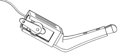
Push until fully seated

Use the servo stopper and two screws to lock the servo in place


- Thread each leg servo wire into the bottom wire guide slot on the chassis. Each leg servo should be matched with a hip servo plus 6. The legs are marked with the hip number near the top and the knee number below that. For example, the leg marked 6 should be threaded through the wire guide on hip servo 0, leg 7 goes with hip 1, leg 8 goes with hip 2, etc. Add 6 to the hip number to get the leg number.
STEP 6: Plug in the Servos
Thread the servo wires into the chassis using the routing holes, as you did with the hip servos. The power distribution harness has marked servo extension sockets for each servo. Each hip servo is marked on the BASE showing its number. the knee servo for each hip is numbered six higher than its corresponding hip. For example, hip servo number 3 will be attached to knee servo number 9, because 3+6=9.
When plugging the servos in, make sure you match the light yellow servo wire to the white servo extension wire, and the dark brown servo wire should match with the black servo extension wire.
STEP 7: Make Robot Electrical Connections
Now use the diagram below in the electrical section to make the rest of the robot's electrical connections. You'll be using the Robot Arduino Nano (marked "R"), the Servo Driver, Bluetooth Module marked "S", the buzzer, and a bunch of jumper wires. Make sure you use the longer jumper wires for the SDA and SCL connections between the Nano and the Servo Driver.
STEP 8: Assemble the leg hinges

Each leg hinge is composed of two identical U-shaped parts. Take one in each hand and align the two so that the bump (shown in the diagram at the right) are both near each other. Turn one 90 degrees with respect to the other.
- Gently squeeze each piece between thumb and forefinger, which causes the little jaws in the center to open up slightly. Work the two halves together. Keep squeezing harder until the ends slide into place. NOTE: Make sure you printed version V1r2b or later. Earlier versions made it too difficult to squeeze the parts into place. If you printed an earlier version, you may need to trim some plastic using angle cutters to get the parts together.
- If you used PLA and are finding it hard to bend, briefly soaking the pieces in very hot tap water has been reported to make it easier. Take care not to scald yourself, the water does not have to be boiling, just hot from the tap. You only need to dip the ends that will lock over each other, not the parts you will squeeze. Use caution.
- At this stage, you may notice that the parts are loosely clamped on each other (this depends on plastic used and whether your printer over- or under-extrudes). Don't worry! When you place the leg hinges over a servo, the servo will spread it apart and they will lock together tightly.
- Insert a 608 skate bearing into the socket on one side of the leg hinges. Pliers may be necessary to press them into place. Make sure you clean up any drips inside the recessed area for the skate bearing before attempting to insert the bearings.
STEP 9: Attach Leg Hinges
The leg hinges connect the hips to the knees. They only go on one way. If you made sure to align the bumps when assembling the leg hinges, this will result in correct orientation of all legs.
- First place the end that matches the servo horn on about halfway. Make sure the servo horn slides under the little pocket at the end of recessed area that accepts the horn.
- Very slightly bend the U shaped piece while pulling the skate bearing side over the hemispherical bump on the other side of the servo holding area. It's a little easier to do the knees (servos mounted to legs) first, followed by the hips (servos on base).
- NOTE: It will be a tight fit, but it should not be excessively difficult to push the hinge over the hemispherical bearing. If you find you are struggling, that means the hinges are too tight. This may affect walking. This can be due to the kind of plastic you used or how your printer is adjusted. You may need to gently spread the two legs of the U shape by hand before putting the hinge on the robot. Be careful of course not to break the hinge.
- When completed, double check to make sure the servo horn went into the covered pocket at the end of its recessed area. This pocket keeps the horn from slipping out of the hinge during stressful operations.
STEP 10: Enclose the electronics modules in their caddies
Now things look pretty messy with all those wires hanging loose, let's clean it up by stowing the Arduino Nano, Bluetooth module and Servo Driver in their caddies. The caddies will keep them safe by making sure they can't short out against each other or touch screws, etc.
- STEP 10A: Insert Caddy Bars Insert the electronics caddy bars as shown in the diagrams below. Notice carefully how they are inserted. Don't insert them upside down, the little hump should be facing inward toward the caddy. You may need to slightly squeeze the forked section at the end to work it into the hole. Once inside, it may be difficult to remove because it will snap into place, so be sure you're putting it in the right way.

Insertion of the caddy bar into the Nano caddy. Notice the orientation, don't put the bar in upside down. The same technique is used for the Servo Driver Caddy.

- STEP 10B: Insert the Arduino Nano into its caddy Carefully insert the Nano as shown, making sure you don't pull out any of the wires. You may need to wiggle the caddy bar from side to side a bit so that components can slide past it during insertion. Notice that the end of the Nano that has the USB port must go in last.

Insert the Nano in the orientation shown.

You may need to wiggle it a bit or press on the bar to work it into place.

Note how the USB port is accessible through the top after full insertion.


- STEP 10C: Insert the Servo Driver into its caddy Carefully insert the Servo Driver as shown, making sure you don't pull out any of the wires. You may need to wiggle the caddy bar from side to side a bit so that components can slide past it during insertion. Notice that the end of the Servo controller with wires sticking out of it must go in last.

Insert the Servo Driver in the orientation shown.

You may need to wiggle it a bit or press on the bar to work it into place.

Note that the end with the wires goes in last.


- STEP 10D: Insert the HC05 Bluetooth Module The diagrams here do not show the wires to make them easier to visualize. The HC05 Bluetooth module with a name beginning with "S" should be used for the robot. For example, the label will read something like "VORP S2944" (the number will differ). The one marked "M" will be used for the gamepad. Slide the HC05 into the side drawer as shown. When inserting, be careful not to pull out the wires, which will be a little tight. Work the wires into the little space provided so they stay clear of the robot's cap when it gets screwed on later.

Insert the HC05 into the side drawer of the Nano Caddy as shown.

When fully inserted, the indicator light will still be visible through the small oval.

The wires should be tucked into the little cavity near the pins of the HC05.


STEP 11: Power up!
Make sure the on/off switch is off, and the knob is turned to STOP. Insert batteries and power on the robot using the on/off switch. You should hear a beep, a pause, then a second beep. The servos should all twitch into position. If the robot does not move at all, immediately turn the switch off and check your connections again. If some of the servos don't move then gently push them with power off to see if you can free them up. If they still won't move, try pushing them with power applied, but turn off the power within 30 seconds if they're locked up. If you can't get the servo to move it will need to be replaced.

STEP 12: Insert Servo Horns
The servo horns are all at random angles right now due to the servo pre-check. In this step we'll make them point in the right direction. The knee servos are not at 90 degrees when the knob is all the way counter clockwise, rather they are at a 30 degree standing angle.
We need to get them to 90 degrees so its easy to align the servo horn, and this is done by going into "Adjust Mode". Turn the knob very slightly clockwise until you hear a beep, then stop. After about one second you will see all the knee servos twitch. This is "adjust servo horn mode". All servos (knees and hips) are now at their halfway point, 90 degrees.
Now you need to take each single arm servo horn and carefully insert it on the shaft so that it is sticking straight out as shown in the figure. You will not always be able to make the horn come totally straight out. This is because there are only 22 little groves (splines) in each shaft, meaning you can in general only come within about 8 degrees of being at a perfect 90 degree angle. This amount of error is acceptable for now, just get it as close as you can. Later we'll use Trim Mode to make fine adjustments.
STEP 13: Test Knee Positions
Turn the knob fully counter clockwise (to STOP) and the robot will go into "stand still" mode. Place it on a level surface such as a table top. Do all of the legs touch the ground? If one or more legs don't touch the ground, you need to adjust the servo horn on the knee a little bit so it does touch. Gently pull off the servo bracket. Pull the servo horn off, and put it back on just a little bit moved so the leg would move closer to the ground. Put the servo bracket back on, and see how it looks. Do this until all legs are at least slightly touching the ground. Again, you can't necessarily be perfect due to the 8 degree increments the servo horns can be moved. But you should be able to be close enough that all legs at least slightly touch the ground.
STEP 14: Insert Servo Screws
Now that the legs are adjusted, you can insert the M3x12 screws (with M3 lock washers) into the servo horns to lock them in place. Note that you will NOT be using the screws that were in the little bag the servos came in, you'll be using the separate pack of screws, which are longer than the ones in the servo bag. Do not overtighten these screws, as you could possibly crack the servo brackets. Just turn the screws until you start to feel resistance, then turn a quarter turn more and stop.
STEP 14: Test the Servos
- STEP 14A: Using TST Mode
- To test whether every servo is working, put the robot on something that will lift its legs off the table top, but won't interfere with the legs (a small box, etc.).
- Start with the knob on STOP, then slowly turn it clockwise. You'll hear one beep (Adjust mode), then a second beep (Test mode). Stop turning and the robot will go into "individual servo test mode". In this mode, every hip servo will move, one by one. When all the hips have moved, every leg will move, one by one. You should see every servo move, in order. If some don't move, check your connections. A common error is to plug a servo connector into the servo controller backwards (i.e. the brown wire is matched with the yellow pin instead of the black pin). If the servos do not move in a sensible order, that probably means you plugged a couple of servos into the wrong sockets in the electrical harness.
- STEP 14B: Test Using Demo Mode
- Ok, everything looks good, so time for a full test. Turn the knob to STOP, then put the robot on the floor, somewhere that has at least a few feet of room in each direction. (Caution: it's tempting to do this on a table top, but unless you have a huge table this is not advisable, Max will run pretty fast at some points during the demo.)
- Turn the knob to DEMO, and about one second later the robot will go through a series of movements to demonstrate some of the things it can do. The full demo only takes about 30 seconds, then repeats. Here, you are looking for the robot to, for example, be able to get back up off the floor after doing some of its dance moves.
- If the robot struggles to get off the floor, you may have a battery that is not fully charged, or there may be drips or other obstructions stopping some legs from moving fully. See the Trouble Shooting Guide for more information about different kinds of issues that can occur. That guide was written for the small robot, but most of the things that can go wrong with Max the Megapod are identical to the things that can go wrong with Vorpal The Hexapod.
STEP 15: Store electronics and wires in the Base
Carefully stow the caddies into the base, using any available convenient space. Arrange the servo and other wires so they don't cross any screw holes. The three Base Cover parts can be used to secure everything, however you may not want to put in more than one screw each at this point, until the robot is more fully tested. Be sure the two battery connectors come through the holes provided for them in the Cover parts.

Carefully stow the caddies into the base, being careful not to pull out any wires. Press servo wires into place too, make sure they don't overlap any screw holes.

Place the three covers in place. It is not necessary to screw them down at this point, you may want to wait until the robot is more fully tested. We normally just put in one screw on each component at this point--this makes it easy to get back into the electronics if something needs to be checked.


STEP 16: Assemble the Cap
- STEP 16A: Assemble the Four Cap Parts
- First assemble the three large pieces after removing the support coming out of the center. Be aware that there is a correct ordering to them, the two flaps that stick out near the bottom need to be opposite each other so the cap can slot into the Base and lock in place. Use 7/8" screws to secure the three parts together as shown. There are access holes around the rim that allow the hex key to reach the screws. Use nuts and locking washers to secure the screws.
- Secure the top of the cap onto the bottom three pieces using three 5/8" #6 socket screws and their associated nuts and toothed lock washers.

Arrangement of the four Cap parts. Note that this diagram shows the support in place, this should actually be removed prior to assembly.

Make sure the two flaps at the rim are opposite each other when ordering the three main parts.


- STEP 16B: Put magnets in the Cap Insert a magnet in each magnet holder in the cap. The magnets are marked with a dot on the North pole side. It is important that this dot be showing after installation. In other words, insert the magnet with the non-dot side down. The magnet is about 2mm smaller in diameter than the hole, so you will need to use hot glue (or some other kind of glue that works on metal and plastic) to secure it.
- STEP 16C: Decorate If desired, use a permanent marker to color the Vorpal "V" on top of the Cap. Oil markers work well. On light colors of plastic a black permanent marker will also work.
- STEP 16D: Put Cap on the Hexapod
- Screw the cap on the robot by lining up the tabs with the matching slots in the rim of the base. Turn the cap clockwise to lock it in place. IMPORTANT: Do not press down on the robot to insert the cap when the robot is under power standing on its legs! You can damage the leg motors by doing this. It is best to turn the robot off, and either support the bottom of the Base with one hand and press the Cap on with the other, or set the Base down on the table top or floor with legs out to the sides so they don't take pressure.
- If the cap is too loose and swivels while the robot moves, this can be fixed by putting a bit of tape on the cap's flaps to make them a little thicker. The tightness of the cap depends a lot on printer settings, over- or under-extrusion, etc.
STEP 17: Warning Label
There are two a self-stick choking hazard warning labels in the hexapod parts bag. Peel the backing off one of them and place it on the bottom of the robot, near the center. Retain the second label for the gamepad.
Step 18: Trimming the Servos
When you assembled the servo horns onto the servos, you probably were not able to get them all to come out exactly at a 90 degree angle. That's not your fault: the servo horns only have 22 possible positions in which they can be installed, so at best you can come within plus or minus 8 degrees of perfection.
Now that you have the gamepad working, you can make fine adjustments to the servo positions using "Trim Mode". In this special gamepad mode, you can adjust all the servos. These adjustments are saved in the robot's EEPROM, which is memory on the Nano that retains data even when powered off. So, you only need to trim once.
Complete instructions on how to use trim mode are in the wiki page: Vorpal The Hexapod Trim Mode Guide. That guide was written for the smaller robot, but the instructions are identical for Max the Megapod.
NOTE: although this step is optional, it is recommended because your robot will walk straighter and all the servos will share equally in lifting the robot's weight, which will make them last longer.
Step 19: Assembling Eye Decorations
Glue a magnet into the magnet hole on both sets of eyes. The magnet should have the marked side face down, not showing.
You can use hot glue, "superglue" or any other kind of glue that works on plastic and metal.
Electrical Connections: Robot
NOTES ON JUMPER WIRES
Wire Lengths
There are two different lengths of female-female Dupont jumper wires used to make most connections. The longer ones (20cm) are only used for the Hexapod's accessory port connections. The shorter ones are used for all the connections on the Gamepad and all the connections on the Hexapod between the Arduino Nano, Servo controller and Bluetooth module.
Wire Color Conventions
Please follow these conventions when selecting wire colors:
- For +5V, Vin, and similar positive voltage connections, use either RED or ORANGE.
- For GND and other negative electrical connections, use BLACK or BROWN.
- For the connectors that sit at the mouth of the accessory port (used for optional sensors) colors are suggested below in the instructions. By following these suggestions you will make your life easier when connecting sensors!
- For all other connections, you can use any color you want, it's arbitrary.
If Jumper Wires Are Too Loose
Sometimes you will find a wire whose connector does not grip the pin well enough. It might fall off very easily or just by gravity alone. If that happens, you have a few options:
- There are extra wires in your kit. If you find a wire that's too loose, just use a different wire.
- Using the hex key, you can put the jumper housing on a flat surface then press on the metal showing through the plastic connector, which will tighten up the jumper wire's grip. Don't go too overboard on pressing though or you might make it too hard to insert.
- Alternatively, you could use electrical tape after inserting all the wires on a module (such as the Nano) to effectively attach together all the little plastic female connector housings. In that way, the connectors that do grip will help hold in the ones that are too loose. Some people also like using hot glue for this purpose. (Personally, I don't like using hot glue, as it makes it harder to change connections if you hooked something up incorrectly.)
NANO PIN CONNECTIONS

- Digital IO Pins:
- D0, D1 are reserved because they are used for uploading programs to the robot, so nothing will be connected there.
- D2, D3 No connection.
- D4 Buzzer Signal (white wire)
- D5 through D13 No connection. These pins are reserved for future expansion.
- Analog Pins:
- A0 Potentiometer signal (white wire)
- A1 Potentiometer Power (red wire)
- A2 Potentiometer Ground (black wire)
- A3 No connection.
- A4 Servo Controller SDA
- A5 Servo Controller SCL
- A6, A7 No connection.
- Power Pins:
- +5V pin on Nano connects to any of the +5V RED wires coming from the BEC on the power distribution harness.
- GND pin on Nano connects to any of the GND BLACK wires coming from the BEC on the power distribution harness.
Servo Driver Power Pins
- Port 0 RED pin on the Servo Driver connects to any of the +5V RED wires coming from the BEC on the power distribution harness.
- Port 0 BLACK GND pin on the Servo Driver connects to any of the GND BLACK wires coming from the BEC on the power distribution harness.
Bluetooth Module Power
- +5V on HC05 connects to any RED Dupont connector coming off the BEC.
- GND on HC05 connects to any BLACK Dupont connector coming off the BEC.
Buzzer Power
- Plug the buzzer into the unused port 15 on the servo driver, making sure the red and black wires on the buzzer power match the red and black rows of pins on the servo driver.
Servo Driver

- Connect the 12 servos to power distribution harness connectors marked with port numbers corresponding to the servo marking (0 to 11). Make sure the signal wire (yellow) is oriented correctly and matches the yellow plastic header pin.
- Connect the groups of four white wires which are marked with servo port numbers to the Servo Driver yellow pins, matching the Servo Driver pin number to the port numbers written on the 4-pin Dupont connectors coming out of the power distribution harness.
- Connect one of the +5V RED regulated BEC outputs to the RED port 0 pin of the Servo Driver. Connect one of the GND black pins coming out of the BEC to the BLACK port 0 GND pin on the Servo Driver.
- On one short side of the Servo Controller you will find a VCC and V+ pin right next to each other. Use a shunt (small black connector that goes over two pins) to connect those together if one is not already installed. Without this shunt the Servo Driver will not work.
- SDA and SCL go to A4 and A5 on the Nano, respectively.
Building the Gamepad
The gamepad for Max The Megapod is identical to the Gamepad for Vorpal The Hexapod.
Please see instructions on the Vorpal Hexapod Gamepad Assembly instructions.
Max The Megapod Quick Links
| BUY A KIT | NEWSLETTER | VORPAL FORUM |
|
User Documentation: |
Activities: |
Contact/Press: |