File list
From Vorpal Robotics Wiki
This special page shows all uploaded files.
| Date | Name | Thumbnail | Size | User | Description | Versions |
|---|---|---|---|---|---|---|
| 17:47, 9 July 2015 | Mimsy-build-fig-35.jpg (file) |  |
1.15 MB | Vorpalwiki | Mimsy build figure 35. | 1 |
| 17:46, 9 July 2015 | Mimsy-build-fig-34.jpg (file) |  |
1.22 MB | Vorpalwiki | Mimsy build figure 34. | 1 |
| 17:44, 9 July 2015 | Mimsy-build-fig-33.jpg (file) |  |
1.39 MB | Vorpalwiki | Mimsy build figure 33. | 1 |
| 17:43, 9 July 2015 | Mimsy-build-fig-32.jpg (file) |  |
822 KB | Vorpalwiki | Mimsy build figure 32. | 1 |
| 17:30, 9 July 2015 | Mimsy-build-fig-31.jpg (file) |  |
941 KB | Vorpalwiki | Mimsy build figure 31. | 1 |
| 17:25, 9 July 2015 | Mimsy-build-fig-30.jpg (file) |  |
834 KB | Vorpalwiki | Mimsy build figure 30. | 1 |
| 02:34, 30 June 2015 | Mimsy-build-fig-29.jpg (file) |  |
1.41 MB | Vorpalwiki | Mimsy Build figure 29. The console fits in the two slots on the rear of Mimsy as shown. | 1 |
| 02:29, 30 June 2015 | Mimsy-build-fig-28.jpg (file) |  |
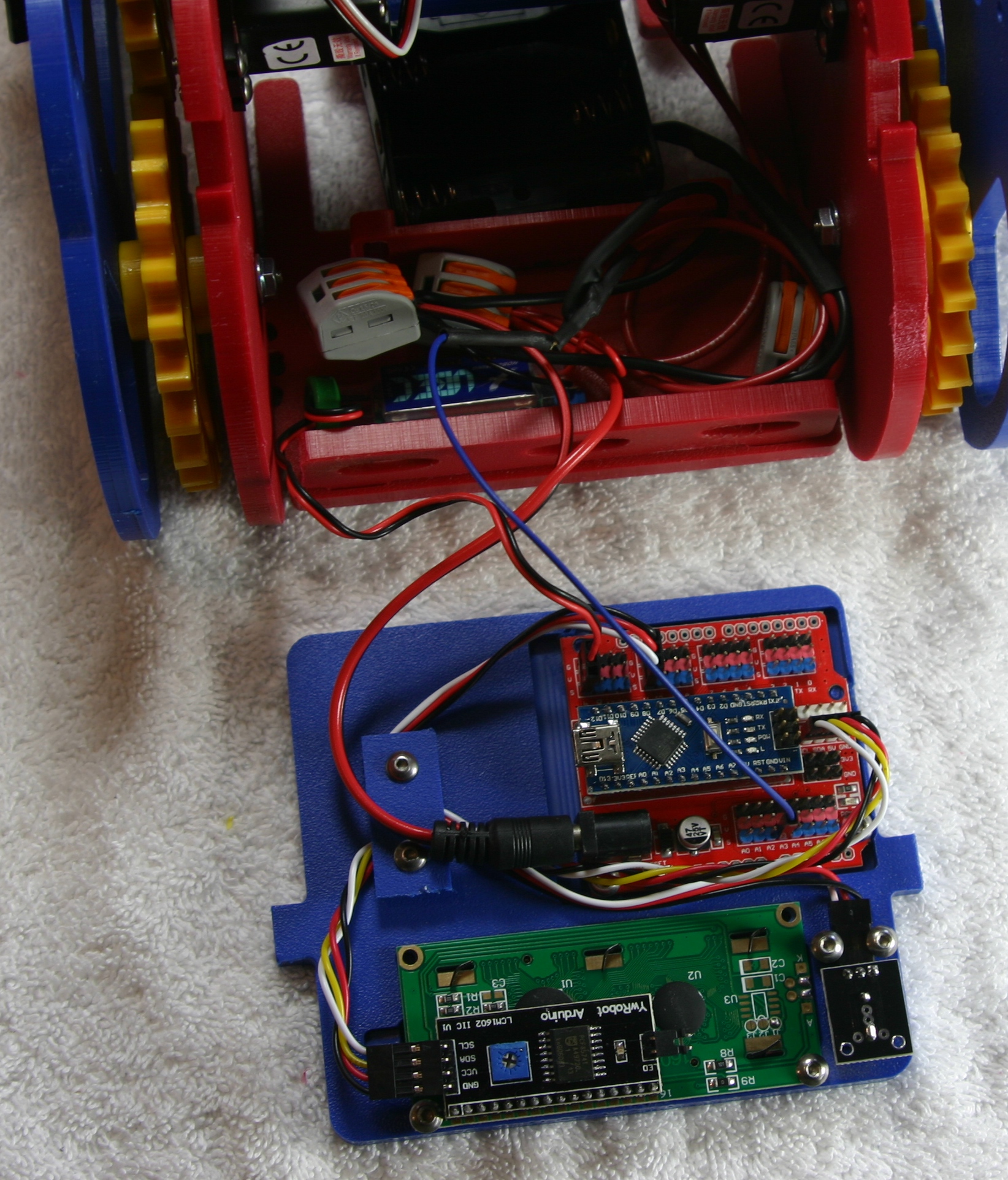
1.48 MB | Vorpalwiki | Mimsy Build figure 28. Route the cables as shown and use the console wire plate and two 3/8" screws to hold them in place. | 1 |
| 02:15, 30 June 2015 | Mimsy-build-fig-27.jpg (file) |  |
1.38 MB | Vorpalwiki | Mimsy Build figure 27. Install the buzzer using two 3/8" screws, do not overtighten. Connect the LCD cable as shown with the black wire at the top. | 1 |
| 02:03, 30 June 2015 | Mimsy-build-fig-26.jpg (file) |  |
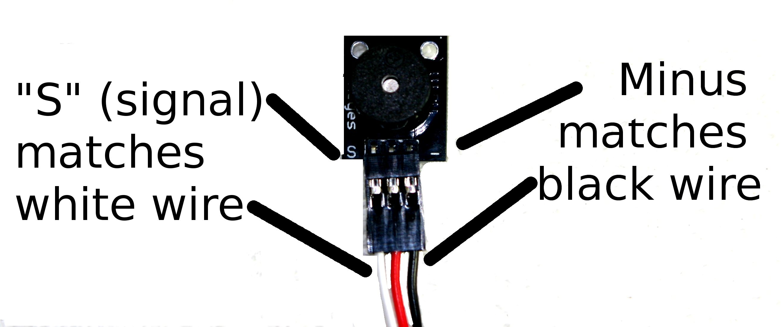
303 KB | Vorpalwiki | Mimsy Build figure 26. Attaching the 10cm 3-wire cable to the buzzer. The black wire matches with the "-" marking while the white matches the "S" marking. | 1 |
| 03:05, 29 June 2015 | Mimsy-build-fig-25.jpg (file) |  |
1.36 MB | Vorpalwiki | Mimsy Build figure 25. The LCD is secured with two screws at the top of the console bezel. | 1 |
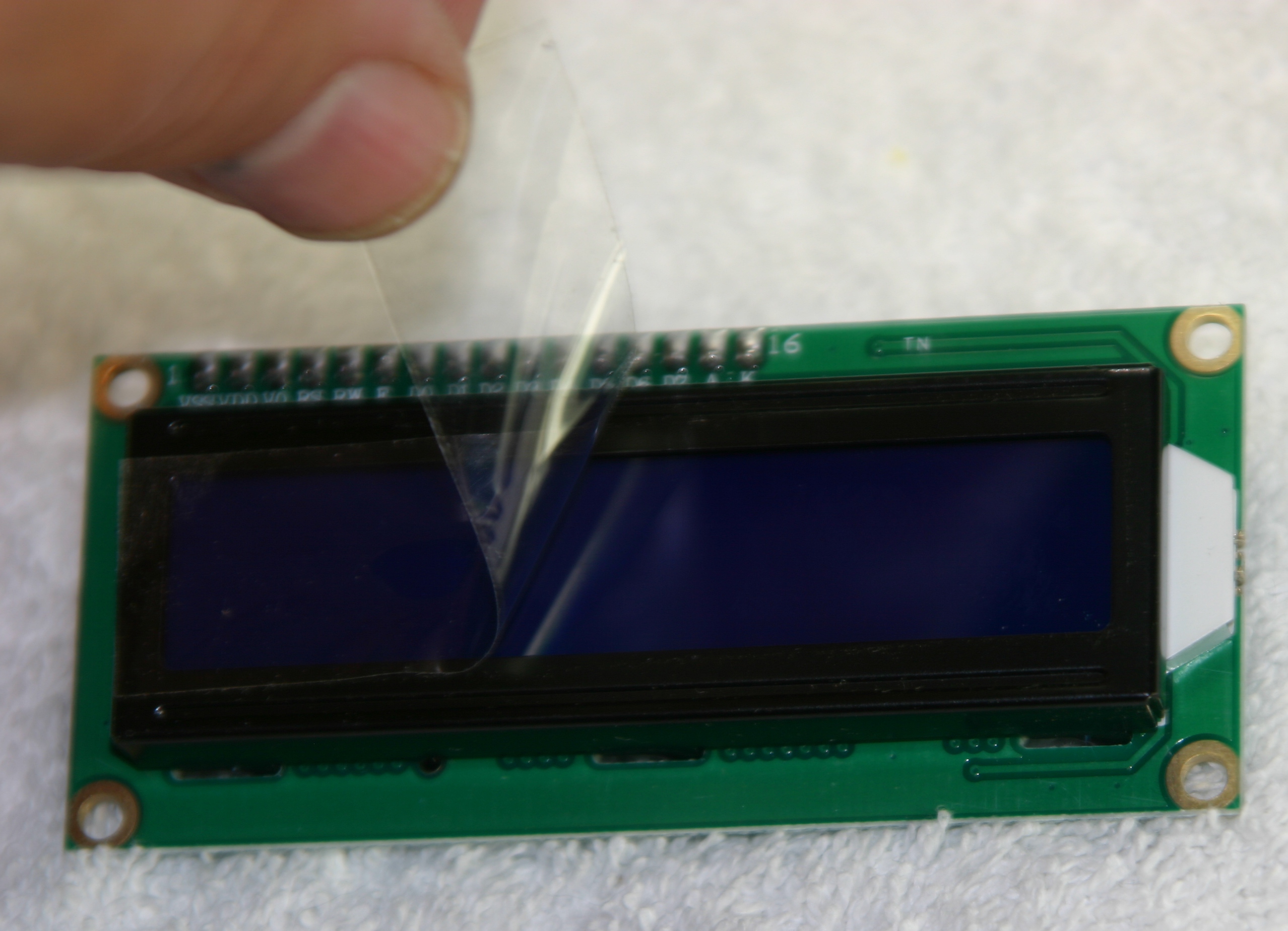
| 02:59, 29 June 2015 | Mimsy-build-fig-24.jpg (file) |  |
965 KB | Vorpalwiki | Mimsy Build figure 24. Remove the protective plastic from the LCD before installing. | 1 |
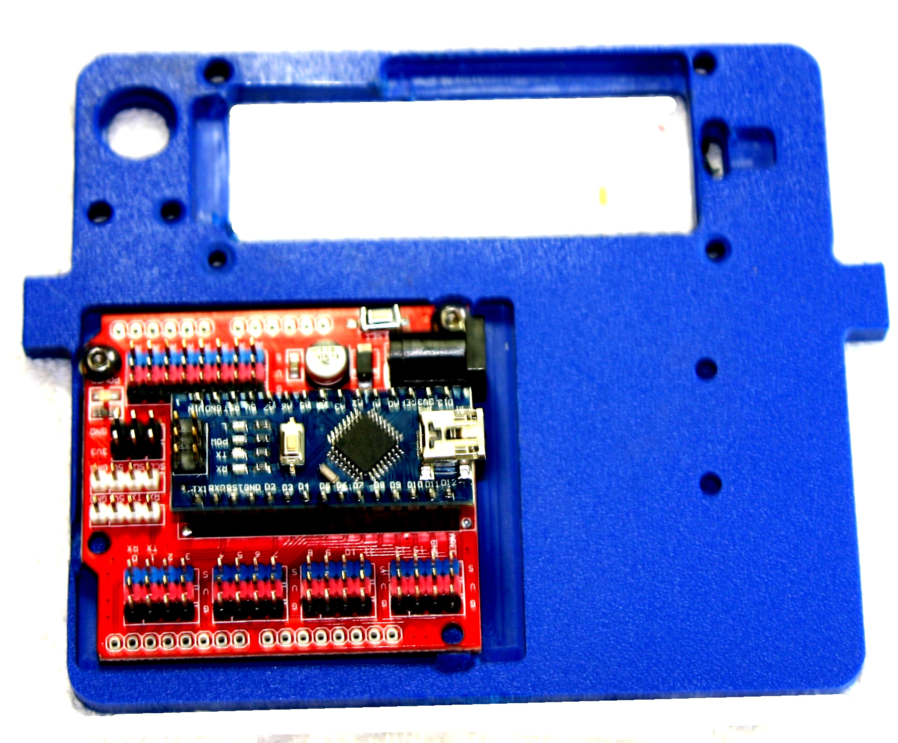
| 02:53, 29 June 2015 | Mimsy-build-fig-23.jpg (file) |  |
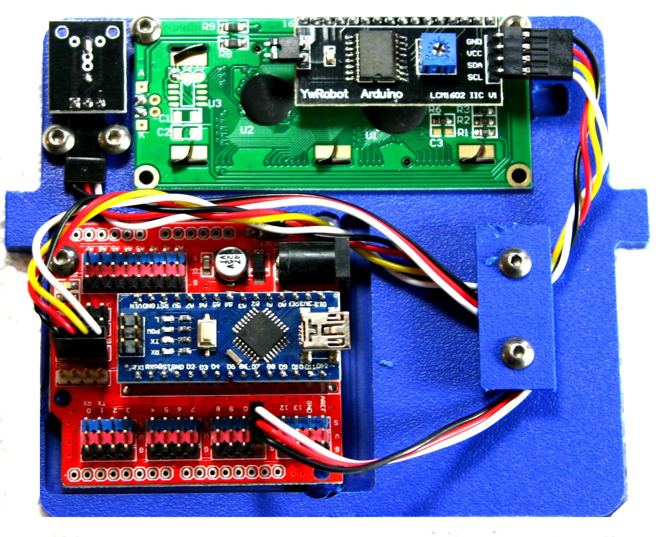
892 KB | Vorpalwiki | Mimsy Build figure 23. Installation of Arduino Nano and IO shield on console. | 1 |
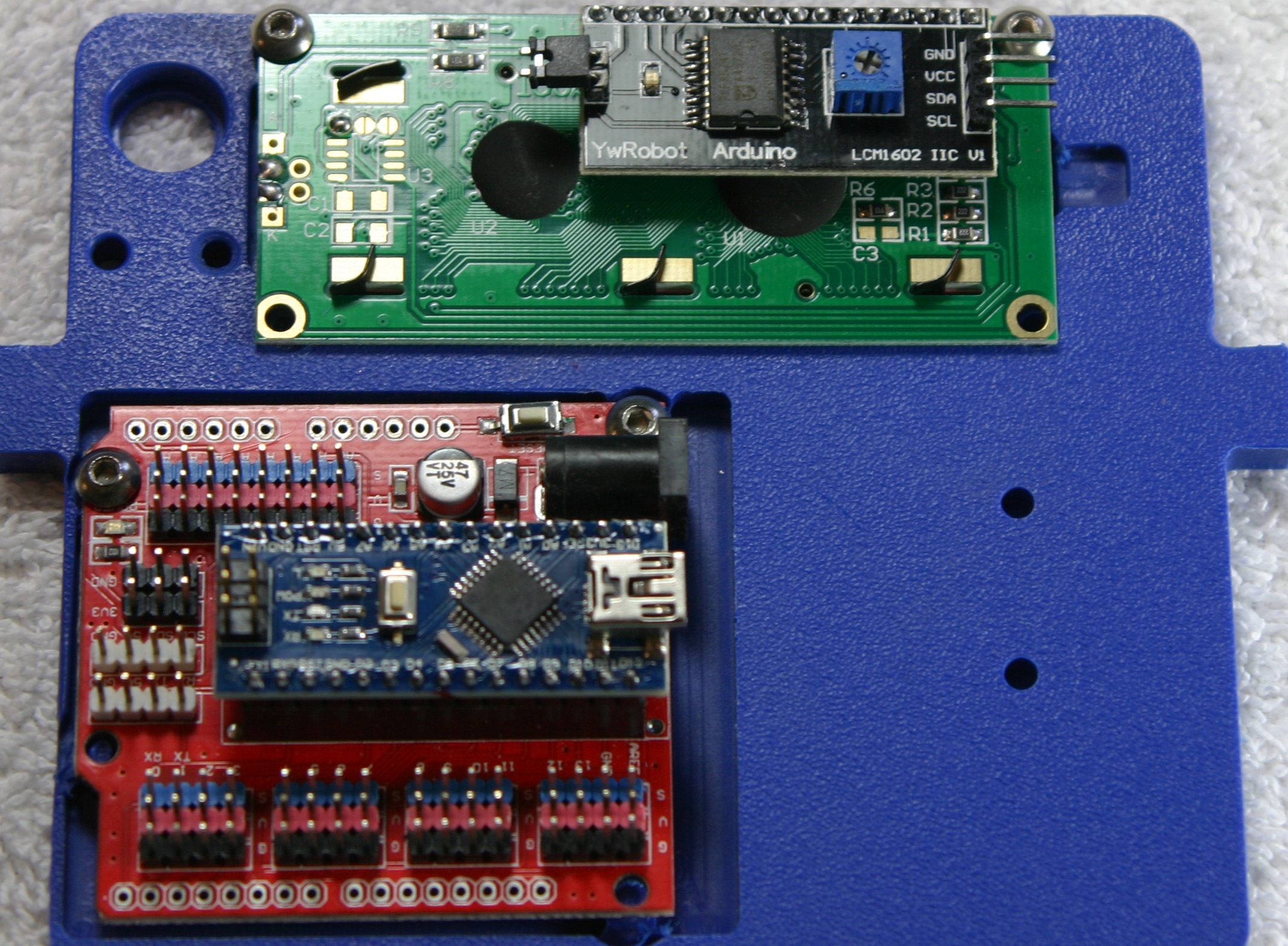
| 02:42, 29 June 2015 | Mimsy-build-fig-22.jpg (file) |  |
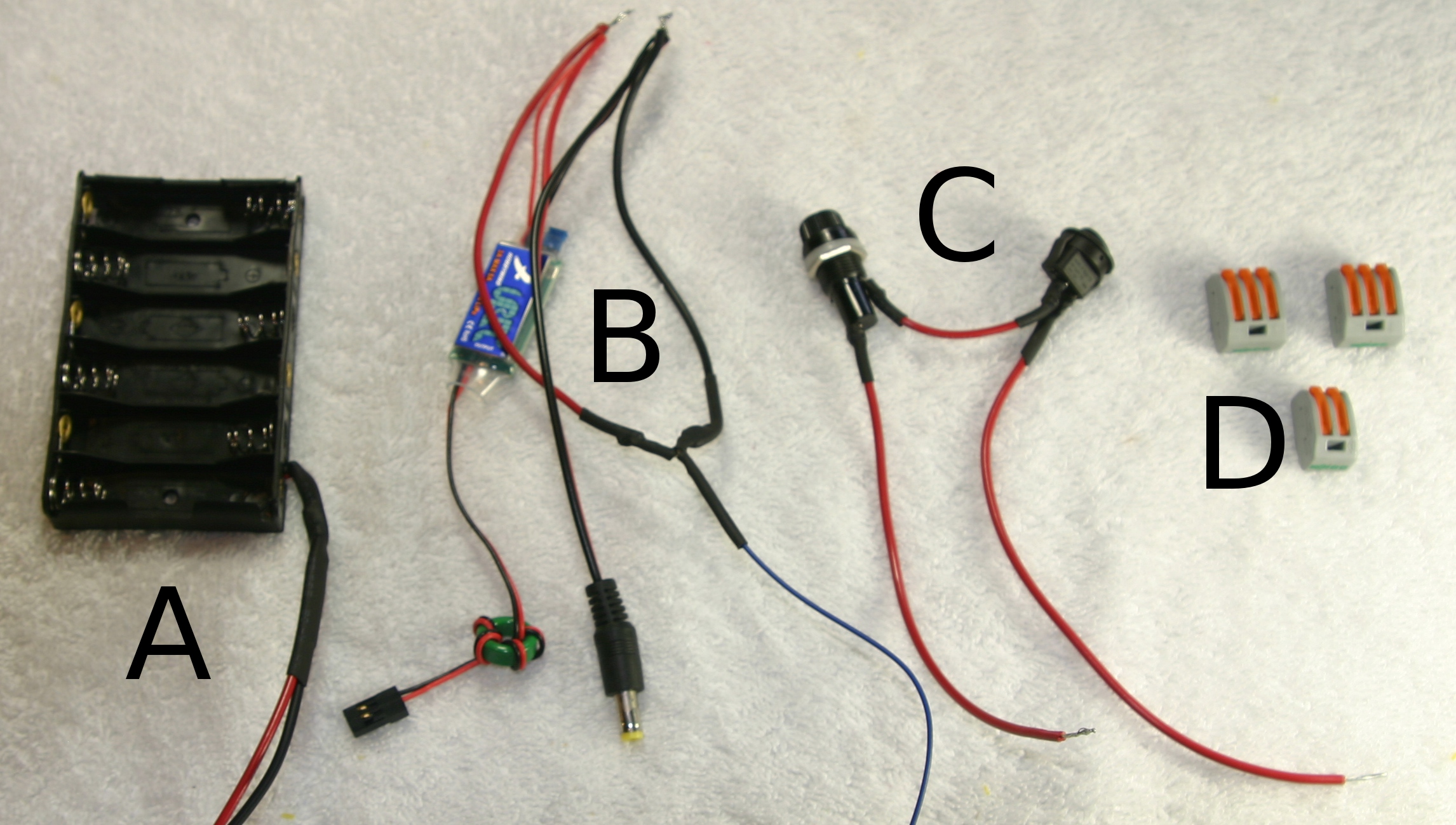
1.33 MB | Vorpalwiki | Mimsy Build figure 22. Parts needed to assemble control panel. | 1 |
| 02:28, 29 June 2015 | Mimsy-build-fig-21.jpg (file) |  |
1.37 MB | Vorpalwiki | Mimsy Build figure 21. The front floor is shown with fence installed. | 1 |
| 02:24, 29 June 2015 | Mimsy-build-fig-20.jpg (file) |  |
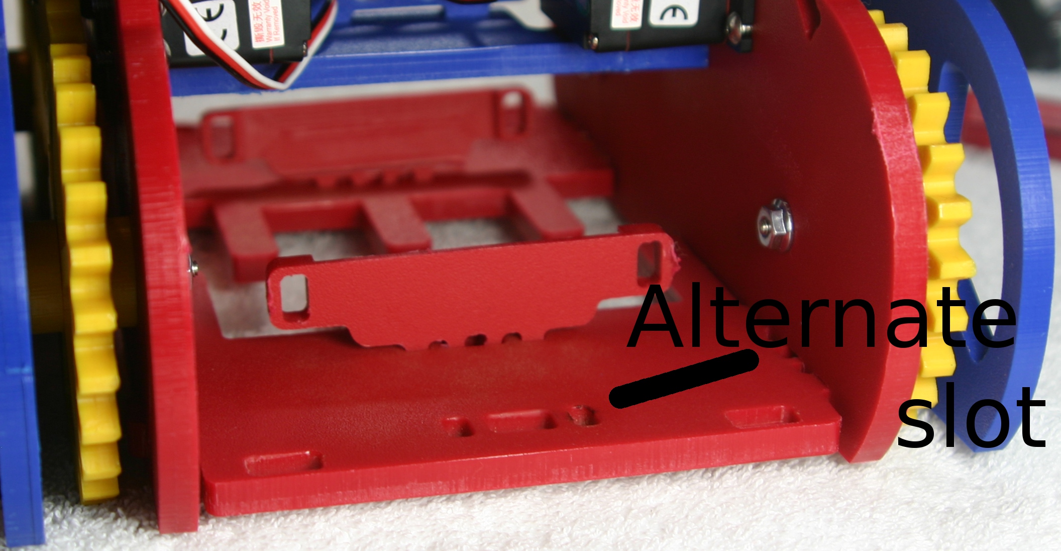
652 KB | Vorpalwiki | Mimsy Build figure 20. Installation of battery brackets. Alternate position is for alternative batteries such as 7.2 volt NIMH RC batteries. | 1 |
| 02:23, 29 June 2015 | Mimsy-build-fig-19.jpg (file) |  |
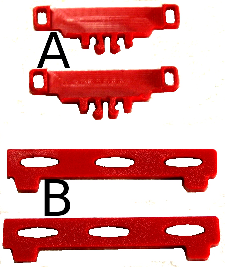
273 KB | Vorpalwiki | Mimys Build figure 19. Parts needed to install battery brackets and fences. | 1 |
| 01:51, 29 June 2015 | Mimsy-build-fig-18.jpg (file) |  |
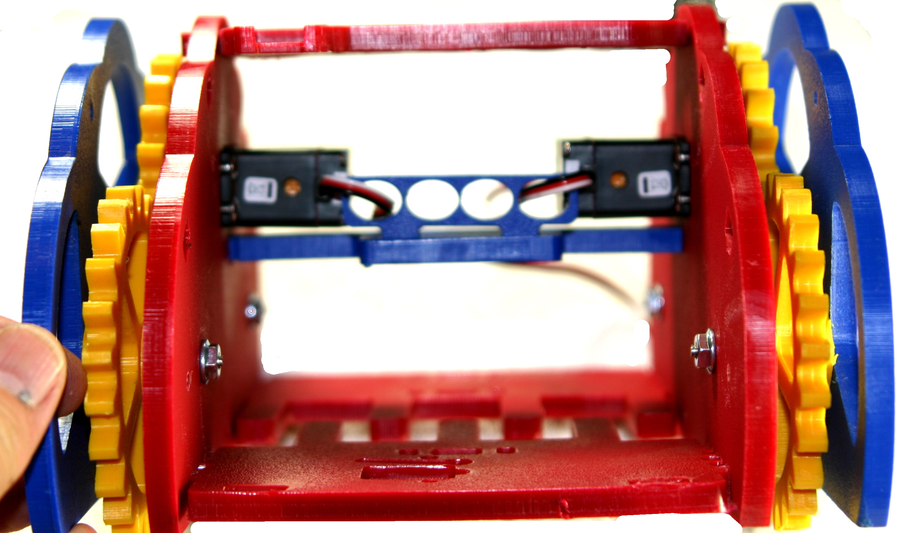
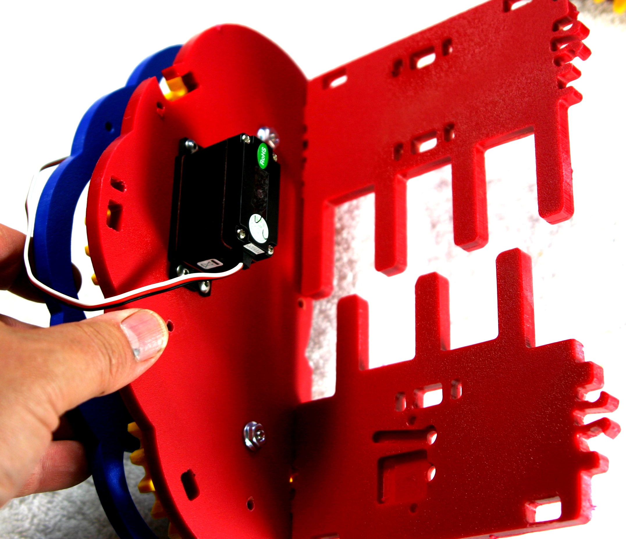
1.27 MB | Vorpalwiki | Mimsy Build figure 18. Front view of chassis with servo wires routed to the rear. | 1 |
| 01:44, 29 June 2015 | Mimsy-build-fig-17.jpg (file) |  |
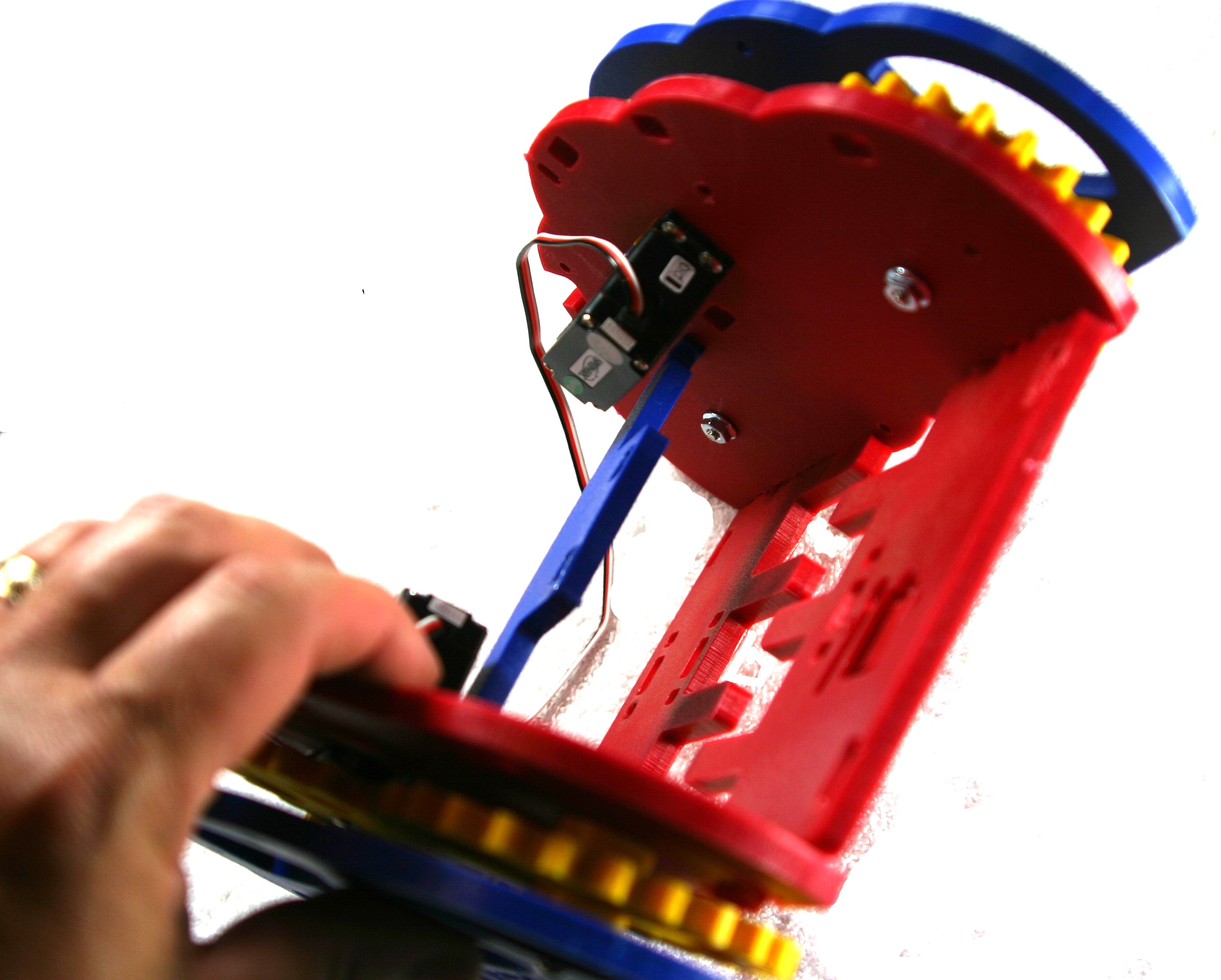
1.09 MB | Vorpalwiki | Mimsy Build figure 17: using the same locking tab and slot system, take the sensor bar and align and press in first one side and then the other. | 1 |
| 01:35, 29 June 2015 | Mimsy-build-fig-16.jpg (file) |  |
800 KB | Vorpalwiki | Mimsy Build figure 16. Insert the cross bar wire guide in the cross bar and firmly press. | 1 |
| 01:31, 29 June 2015 | Mimsy-build-fig-15.jpg (file) |  |
981 KB | Vorpalwiki | Mimsy Build figure 15. Insert the cross bar with the two square holes facing the side of the servos that have the wires. You need to angle it in. Just loosely put both sides in the slots, don't force it forward to lock yet. | 1 |
| 01:10, 29 June 2015 | Mimsy-build-fig-14.jpg (file) |  |
1.08 MB | Vorpalwiki | Mimsy Build figure 14. Front and rear floors installed on one drive train. | 1 |
| 01:06, 29 June 2015 | Mimsy-build-fig-13.jpg (file) |  |
190 KB | Vorpalwiki | Mimsy Build figure 13. Make sure the locking tabs are pushed all the way through the slots so they are firmly connected. | 1 |
| 01:00, 29 June 2015 | Mimsy-build-fig-12.jpg (file) |  |
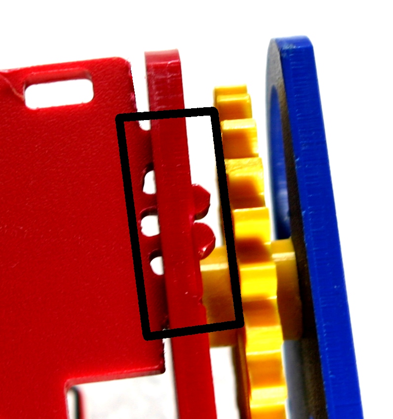
793 KB | Vorpalwiki | Mimsy Build figure 12. The locking tabs will only align one way with the slots in a drive train. Make sure you have the right match-up. | 1 |
| 00:33, 29 June 2015 | Mimsy-build-fig-11.jpg (file) |  |
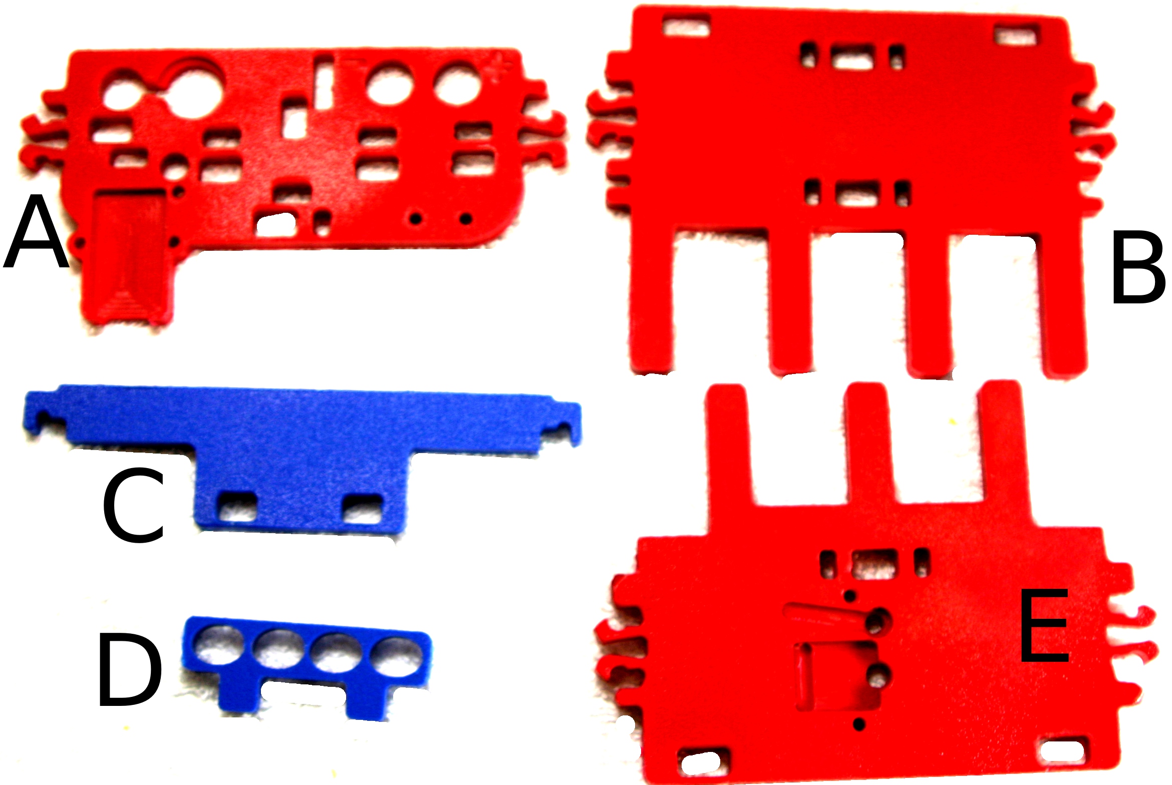
709 KB | Vorpalwiki | Mimsy Build figure 11. Parts needed to join the two drive trains into a single chassis. | 1 |
| 23:46, 28 June 2015 | Mimsy-build-fig-05.jpg (file) |  |
183 KB | Vorpalwiki | 2 | |
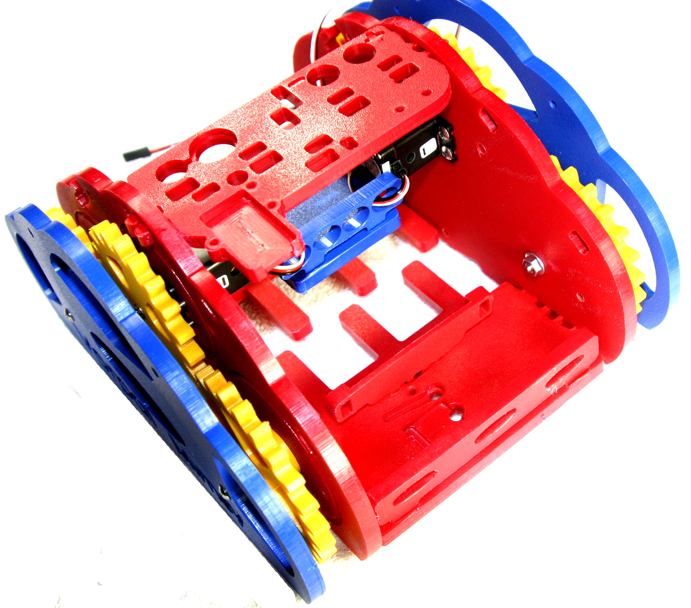
| 23:35, 28 June 2015 | Mimsy-build-fig-10.jpg (file) |  |
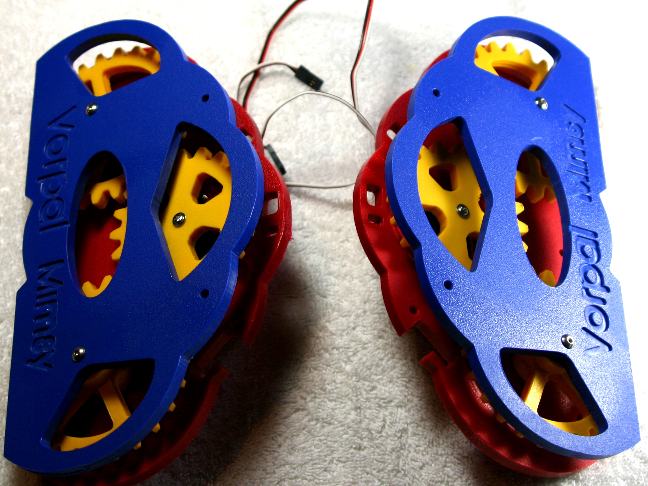
1.2 MB | Vorpalwiki | Mimsy Build figure 10. The two drive trains are now ready to be connected together. | 1 |
| 23:31, 28 June 2015 | Mimsy-build-fig-09.jpg (file) |  |
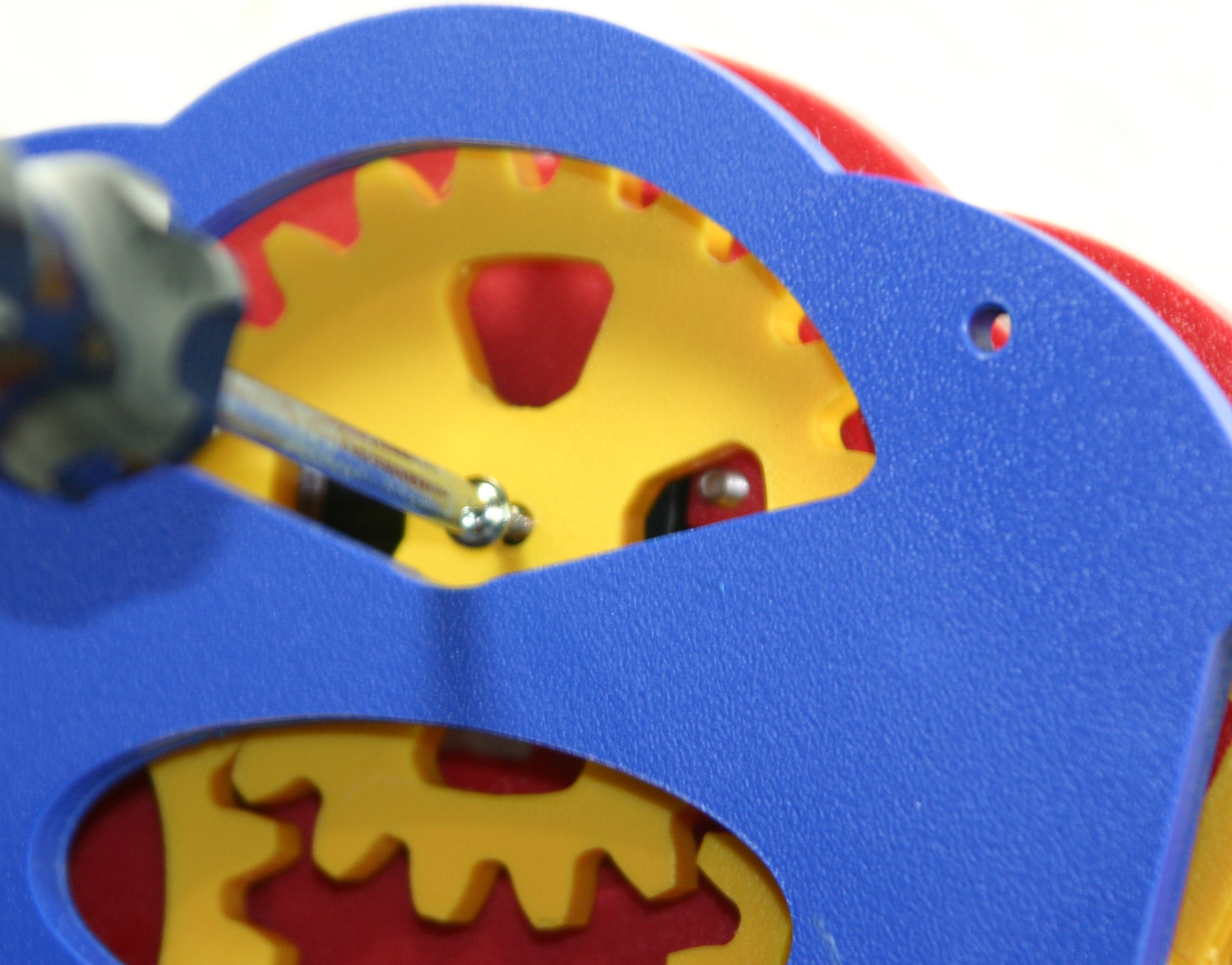
1.59 MB | Vorpalwiki | Mimsy Build figure 9. Secure the 20-tooth gear to the servo using a pointed screw. NOTE: do not use the tiny phillips head screwdriver that came with your kit, that's for adjusting the sound sensor and LCD backlight and it's not strong enough. | 1 |
| 23:25, 28 June 2015 | Mimsy-build-fig-08.jpg (file) |  |
1.75 MB | Vorpalwiki | Mimsy Build figure 8. It's easier to insert the 20-tooth gear with servo horn by holding the drive train with the servo on top. Slide the gear/horn in between the plates and using the large pie-shaped holes on the outer plate, position the gear/horn. Y... | 1 |
| 21:57, 28 June 2015 | Mimsy-build-fig-07.jpg (file) |  |
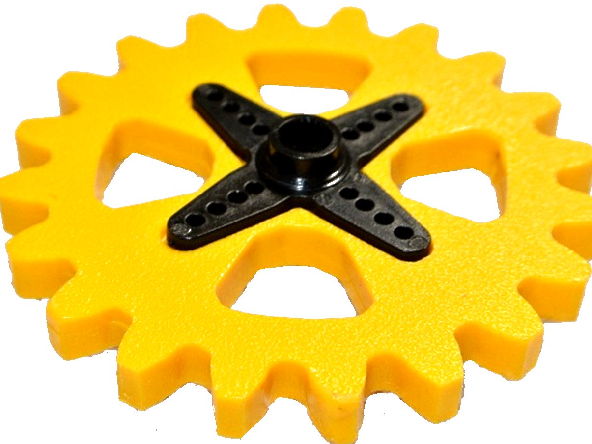
117 KB | Vorpalwiki | Mimsy Build figure 7. Insert the cross shaped servo horn in the matching slot in the 20-tooth gear. Make sure the collar (in the center) is facing up. | 1 |
| 21:40, 28 June 2015 | Mimsy-build-fig-06.jpg (file) |  |
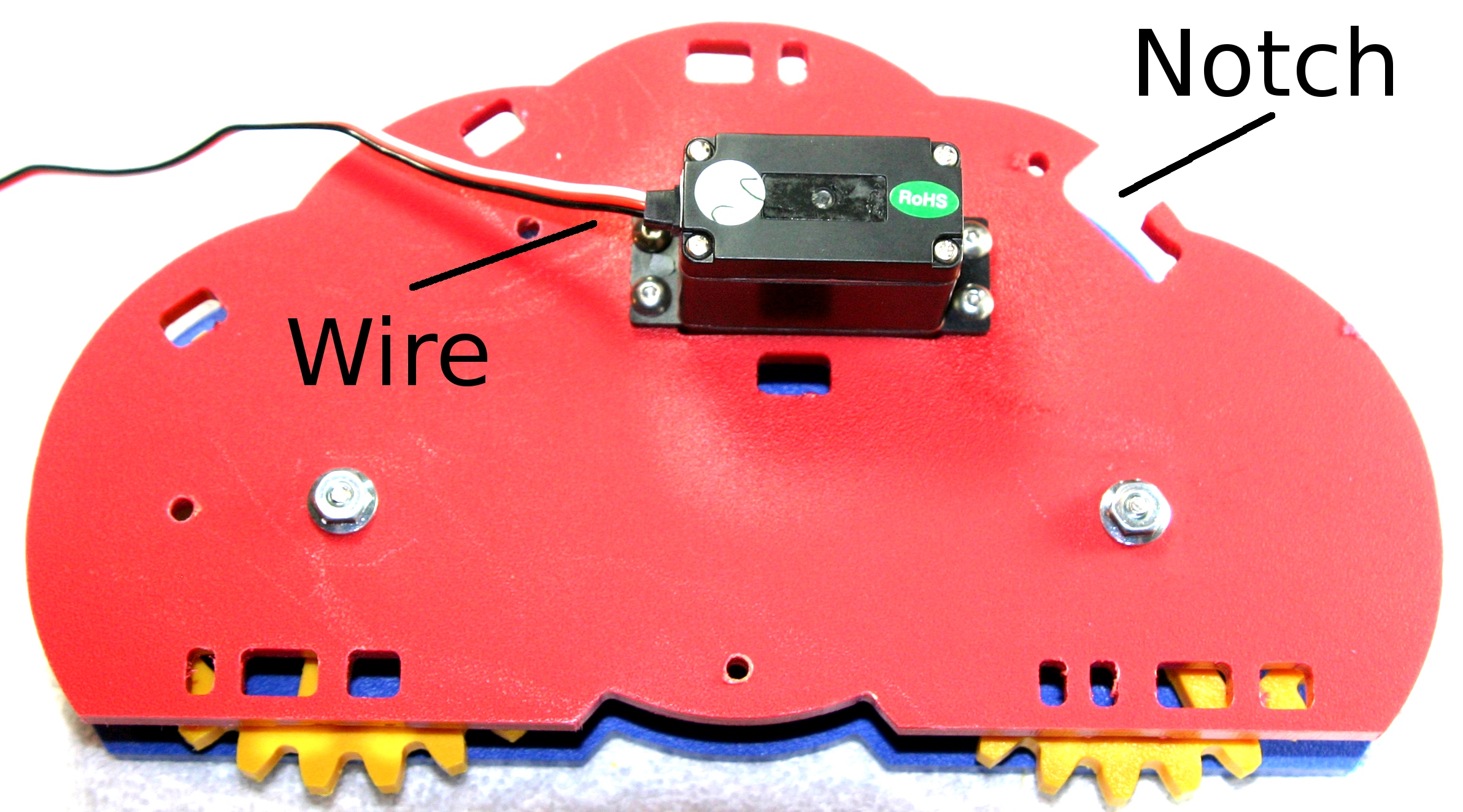
1.02 MB | Vorpalwiki | Mimsy build figure 6. Make sure the servo motor's wire is on the opposite side from the notch in the inner plate. | 1 |
| 13:58, 27 June 2015 | Mimsy-build-fig-04.jpg (file) |  |
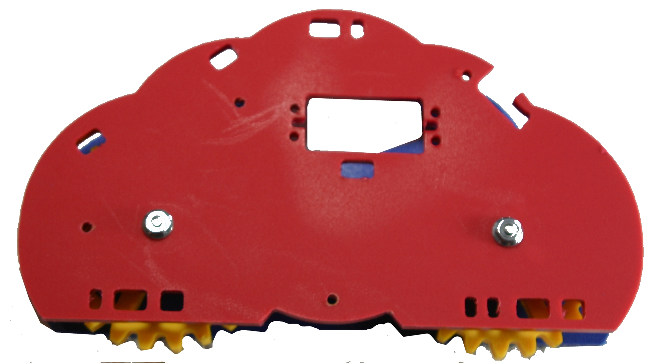
468 KB | Vorpalwiki | Place the inner plate on the screws (with the inscribed circles face down toward the gears) and use the nuts to secure. Proper tension on the nuts is important. The gears should be able to spin for a couple of seconds if you flick them with your hand. ... | 1 |
| 13:39, 27 June 2015 | Mimsy-build-fig-03.jpg (file) |  |
712 KB | Vorpalwiki | 1 | |
| 13:30, 27 June 2015 | Mimsy-build-fig-02.jpg (file) |  |
825 KB | Vorpalwiki | Vorpal Mimsy Build Figure 2. Drive train screws placed on outer plate, white spacer and one large spacer placed on each screw. | 1 |
| 13:03, 27 June 2015 | Mimsy-build-fig-01.jpg (file) |  |
735 KB | Vorpalwiki | 2 | |
| 01:16, 26 June 2015 | Parts-cross-bar-wire-guide.jpg (file) |  |
5 KB | Vorpalwiki | Cross bar wire guide. This part slots into the cross bar and provides oval windows you can feed motor and sensor cables through, keeping them better managed. | 1 |
| 01:14, 26 June 2015 | Parts-cross-bar.jpg (file) |  |
5 KB | Vorpalwiki | Cross bar. This part mounts under the drive train servos and helps lock the two drive train halves together securely. It also keeps sensor and motor wires from falling down on top of the battery pack. | 1 |
| 01:13, 26 June 2015 | Parts-console-wire-plate.jpg (file) |  |
3 KB | Vorpalwiki | Console wire plate. This is simply used to hold down the LCD and buzzer cables on the console. | 1 |
| 01:12, 26 June 2015 | Parts-console.jpg (file) |  |
25 KB | Vorpalwiki | Console. Provides bezel for LCD display, also the buzzler, Arduino Nano, and IO shield mount on it. | 1 |
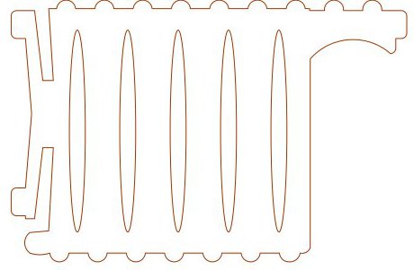
| 01:10, 26 June 2015 | Parts-front-grill.jpg (file) |  |
17 KB | Vorpalwiki | Front grill, used to hide wires. Can be removed without tools to change out batteries. | 1 |
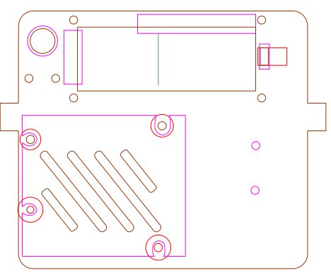
| 00:57, 26 June 2015 | Parts-outer-plate.jpg (file) |  |
29 KB | Vorpalwiki | Mimsy 1.1 Outer Plate rev62 | 1 |
| 02:27, 24 June 2015 | Mimsy-Arduino-Access.jpg (file) |  |
806 KB | Vorpalwiki | 2 | |
| 02:09, 24 June 2015 | Mimsy-annotated.jpg (file) |  |
1.32 MB | Vorpalwiki | Vorpal Mimsy sensors and actuator. | 1 |
| 23:40, 23 June 2015 | MainPage-Mimsy11.jpg (file) |  |
751 KB | Vorpalwiki | 1 | |
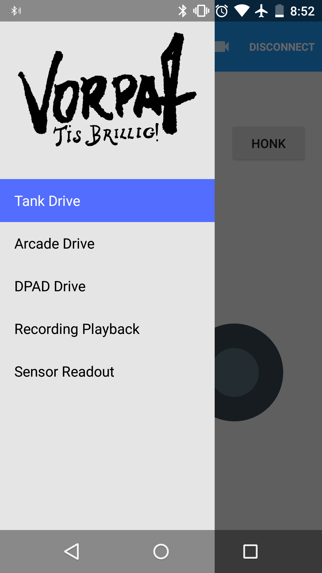
| 17:16, 22 June 2015 | Screenshot 20150620-205225 1.png (file) |  |
107 KB | Vorpalwiki | Vorpal Commander Android App with Drawer Open | 1 |
| 17:15, 22 June 2015 | Screenshot 20150620-205243.png (file) |  |
48 KB | Vorpalwiki | Vorpal Commander Android App in DPAD mode on a small screen device | 1 |
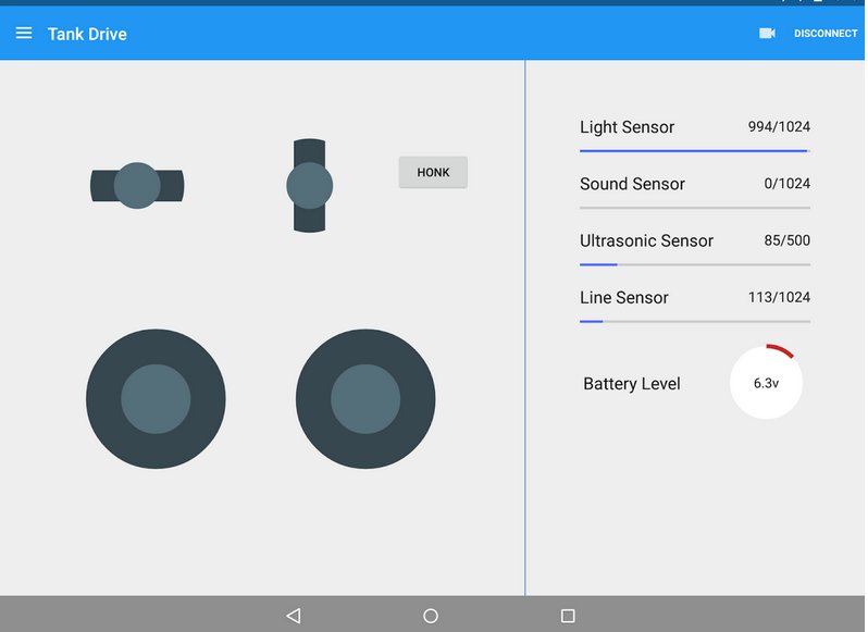
| 17:14, 22 June 2015 | Vorpal-commander-tank-drive.jpg (file) |  |
30 KB | Vorpalwiki | Vorpal Commander Android App in Tank Drive Mode | 1 |
| 17:13, 22 June 2015 | Vorpal-commander-arcade.jpg (file) |  |
30 KB | Vorpalwiki | 1 | |
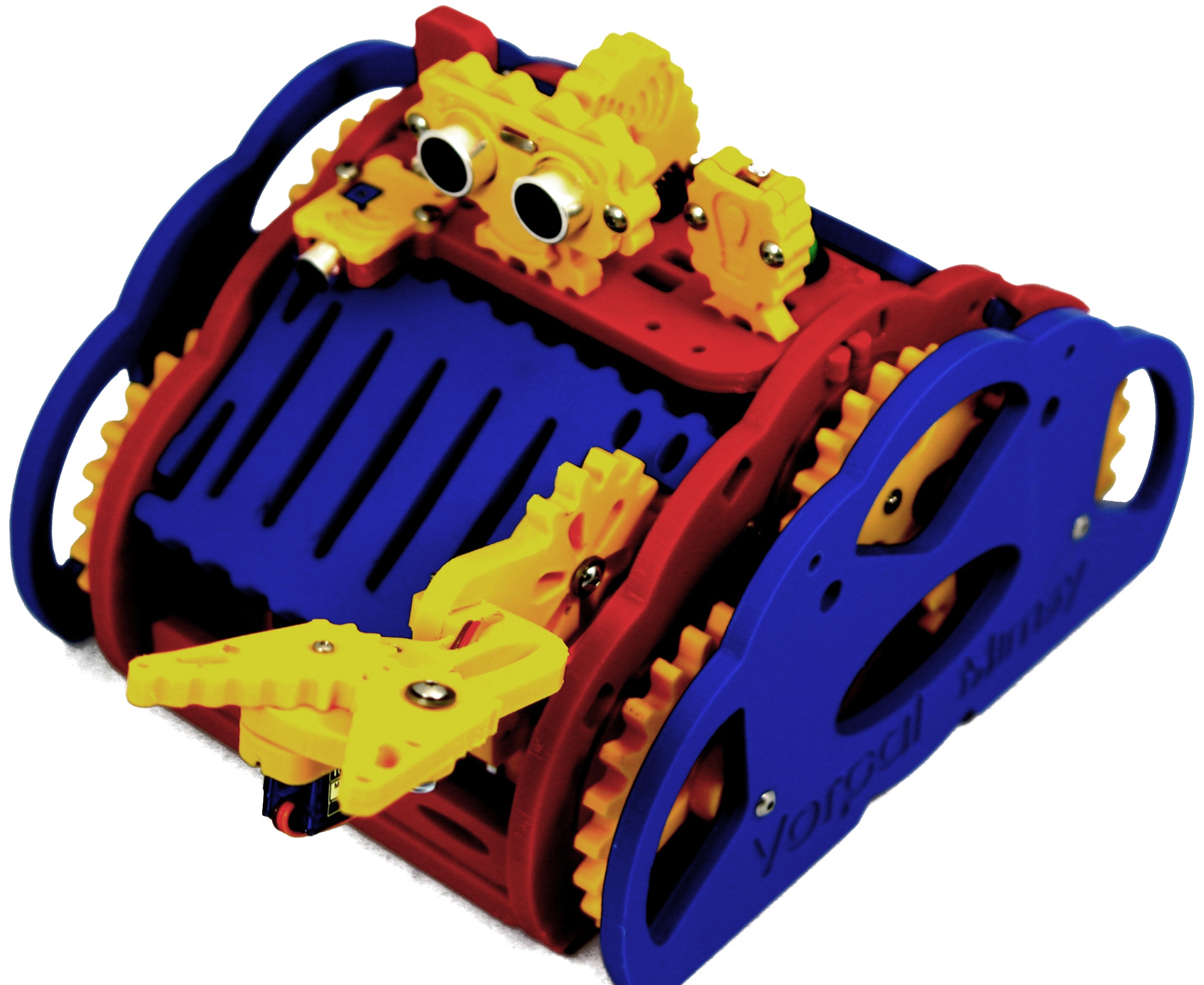
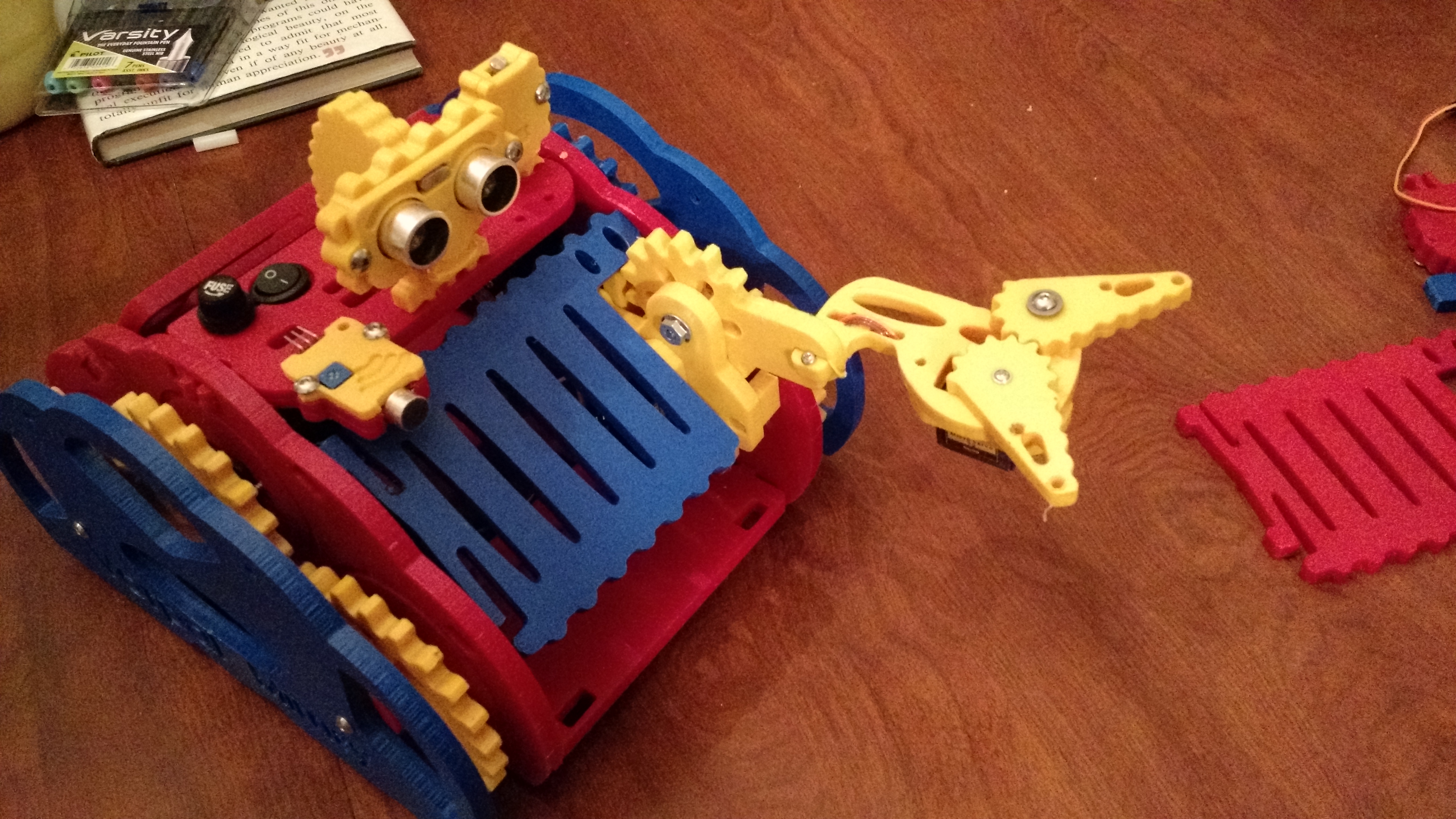
| 17:10, 22 June 2015 | 05-Mimsy-yellow-arm-yellow-sensor-blue-grill.jpg (file) |  |
2.94 MB | Vorpalwiki | Vorpal Mimsy with yellow and blue theme | 1 |
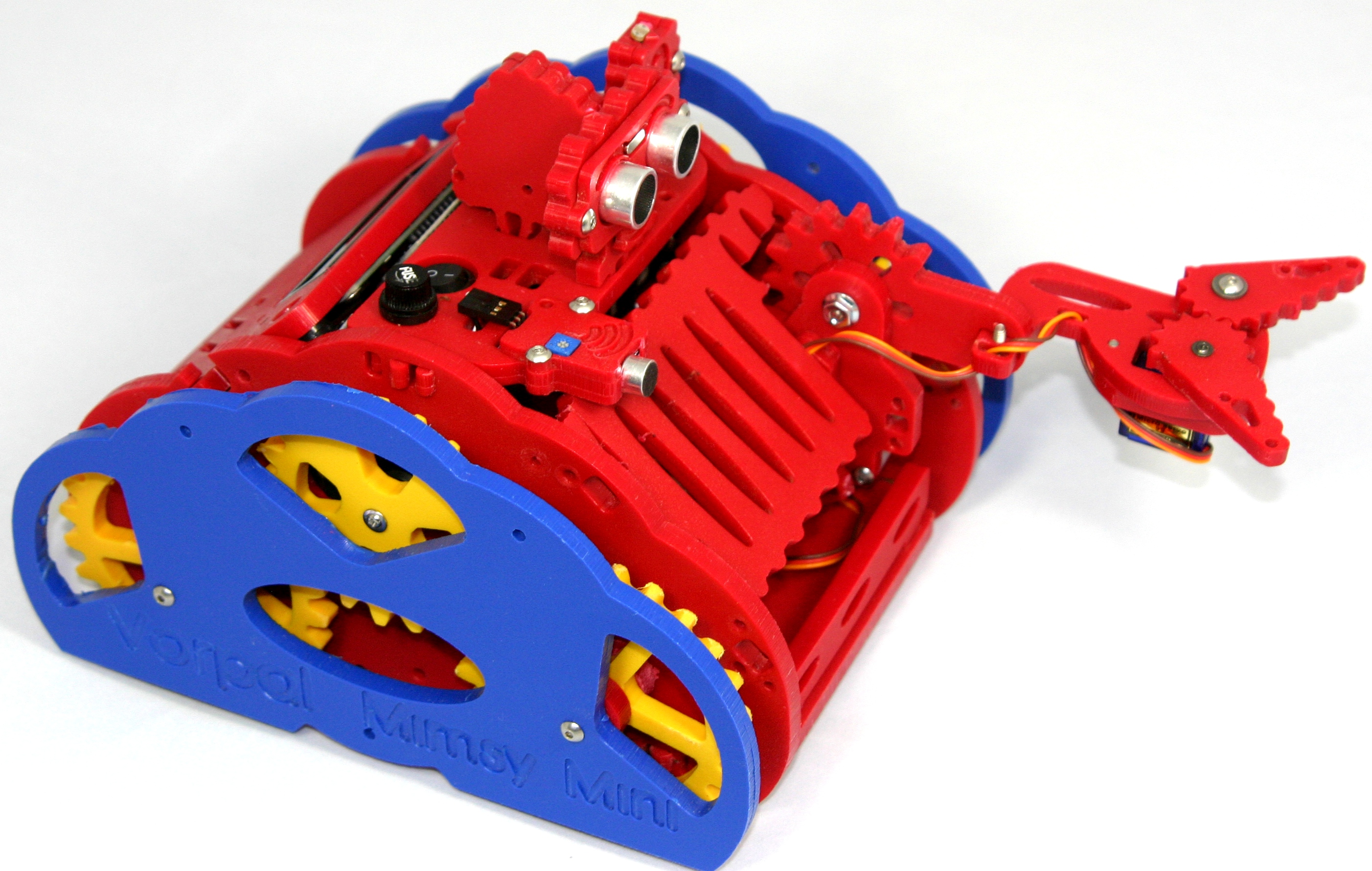
| 16:59, 22 June 2015 | 01-mimsy-all-red-center.jpg (file) |  |
1.5 MB | Vorpalwiki | Vorpal Mimsy 1.1 with all red parts down the center of the robot. | 1 |