File list
From Vorpal Robotics Wiki
This special page shows all uploaded files.
| Date | Name | Thumbnail | Size | Description | Versions |
|---|---|---|---|---|---|
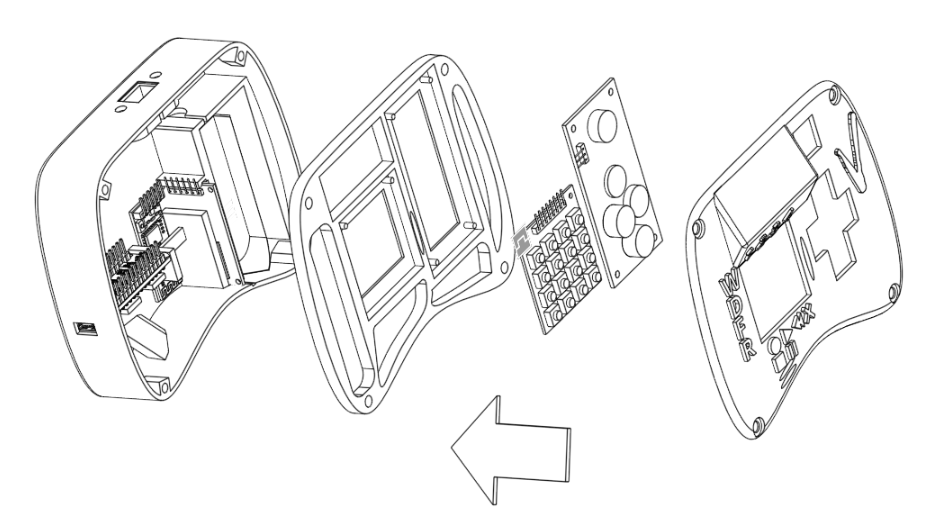
| 02:03, 31 July 2017 | Gamepad-Overall-Assembly-Exploded.png (file) |  |
241 KB | 1 | |
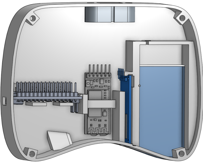
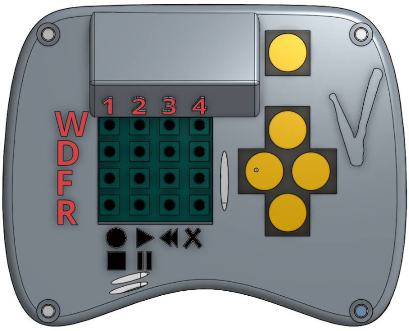
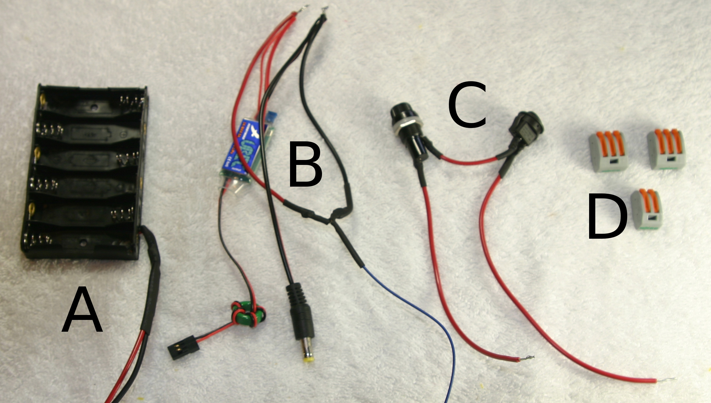
| 01:12, 31 July 2017 | Gamepad-Electronics-Layout.png (file) |  |
209 KB | 1 | |
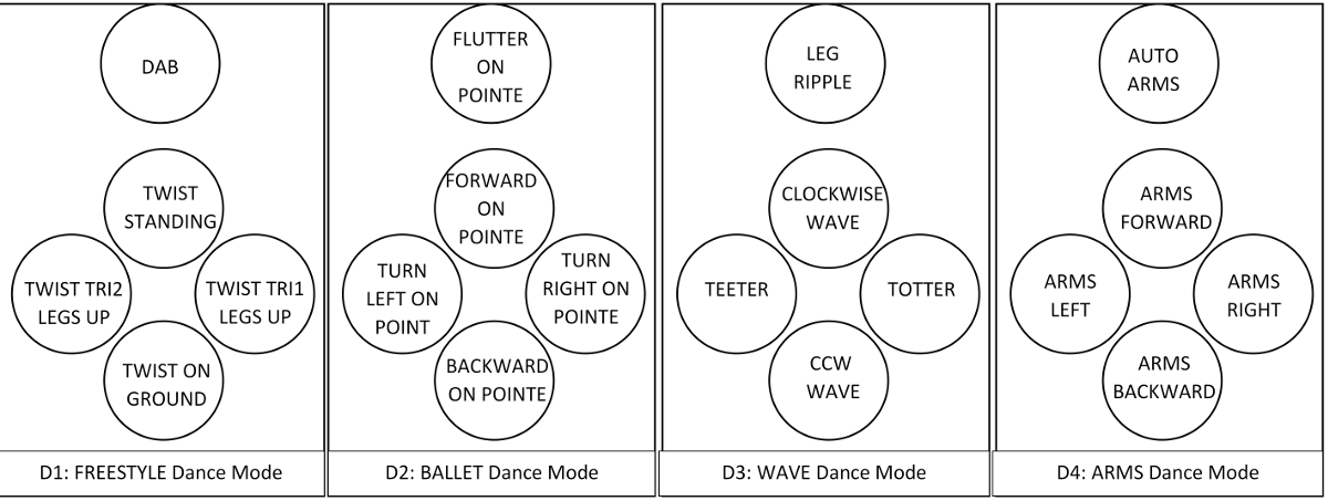
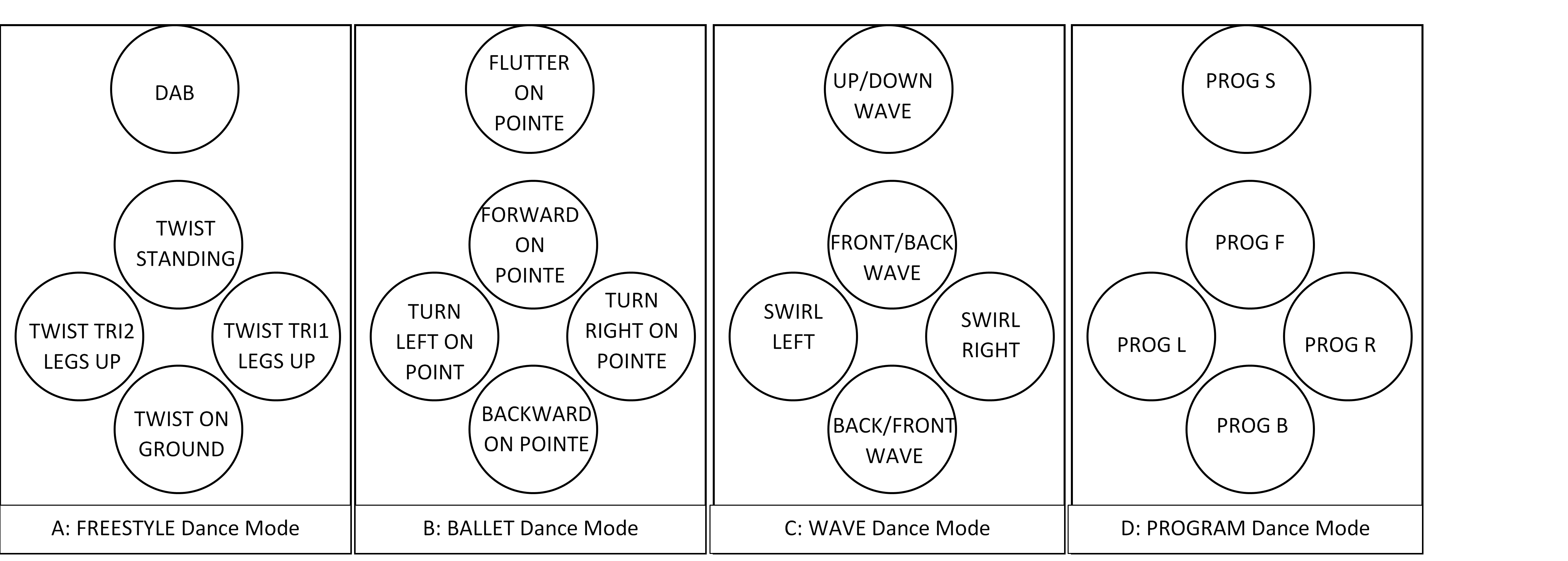
| 02:58, 30 July 2017 | DPAD-Dance-Modes-v2.png (file) |  |
163 KB | 1 | |
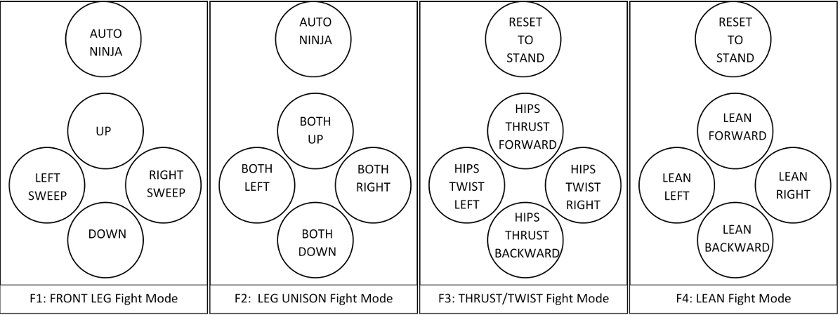
| 02:32, 30 July 2017 | DPAD-Fight-Modes-v2.png (file) |  |
155 KB | 1 | |
| 02:20, 30 July 2017 | DPAD-Dance-Modes.png (file) | Error creating thumbnail: File with dimensions greater than 12.5 MP |
563 KB | 1 | |
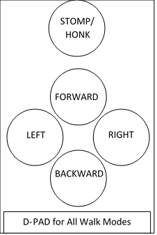
| 01:56, 30 July 2017 | DPAD-for-Walk-Modes.png (file) |  |
19 KB | 1 | |
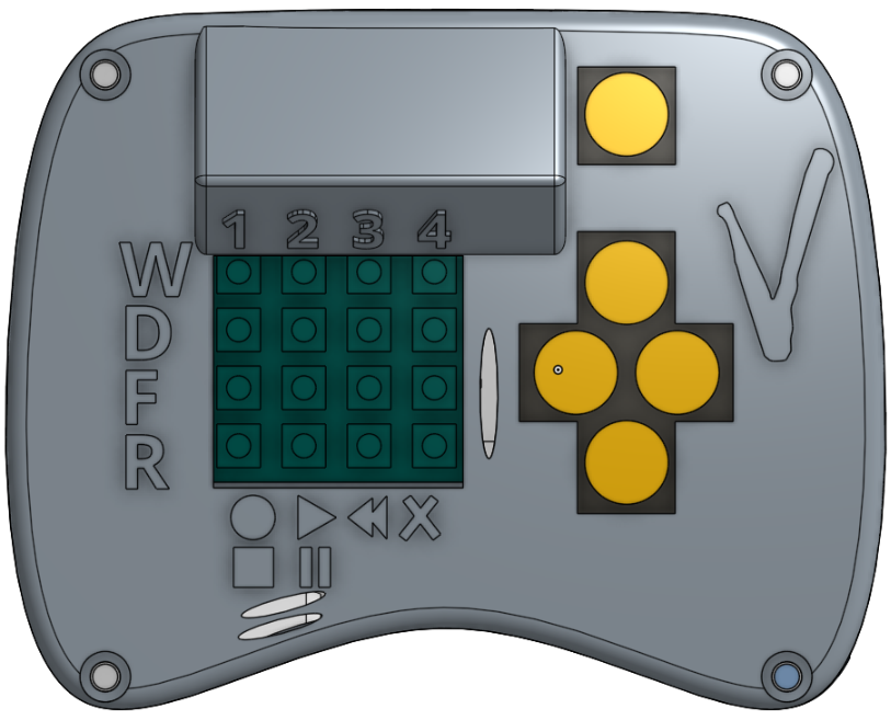
| 00:41, 30 July 2017 | Gamepad-Top-View-v2.png (file) |  |
257 KB | 2 | |
| 00:39, 30 July 2017 | Gamepad-Top-View.png (file) |  |
262 KB | 3 | |
| 00:39, 30 July 2017 | Gamepad-Function-Diagram.png (file) |  |
153 KB | 2 | |
| 14:56, 26 July 2017 | Choking-Hazard-Image.jpg (file) |  |
27 KB | 1 | |
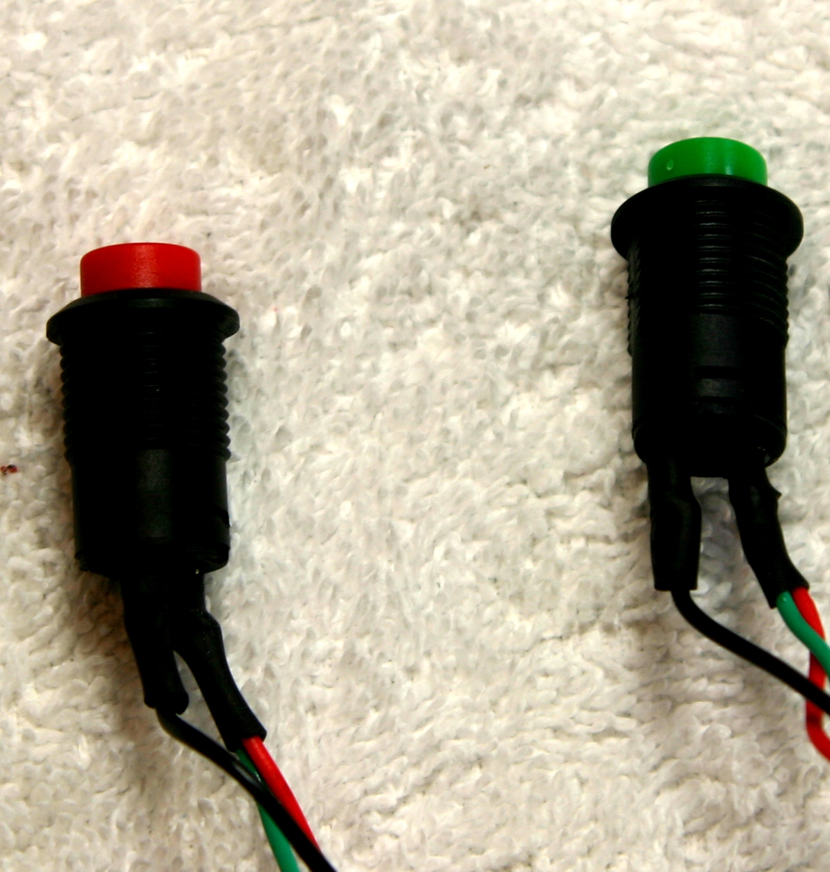
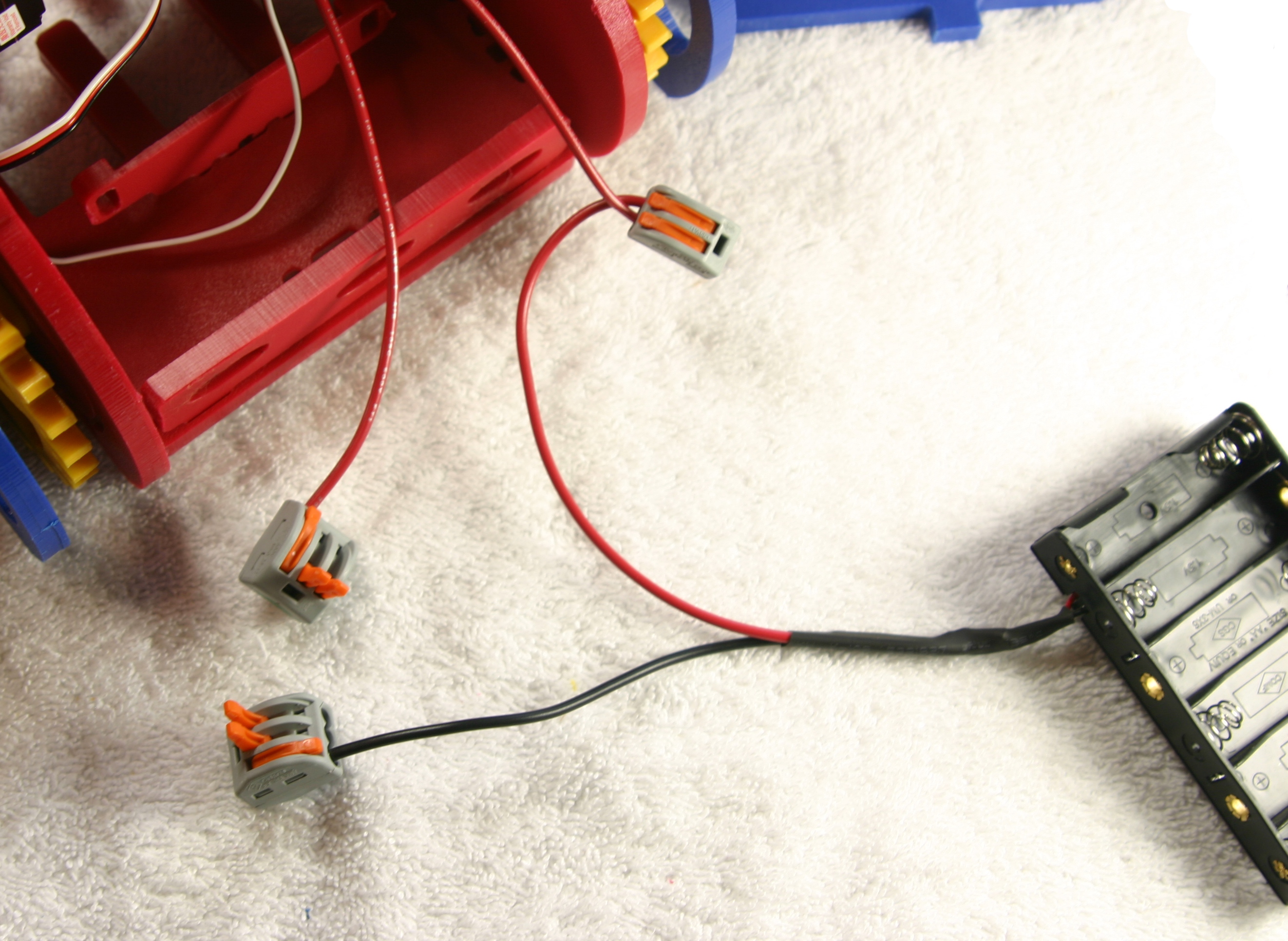
| 18:32, 25 July 2017 | Gamepad-Electrical-Switch-Assembly.jpg (file) |  |
16 KB | 1 | |
| 16:39, 21 July 2017 | CC-NC-BY-SA-88x31.png (file) |  |
2 KB | 1 | |
| 16:31, 21 July 2017 | CC-BY-SA-88x31.png (file) |  |
2 KB | 1 | |
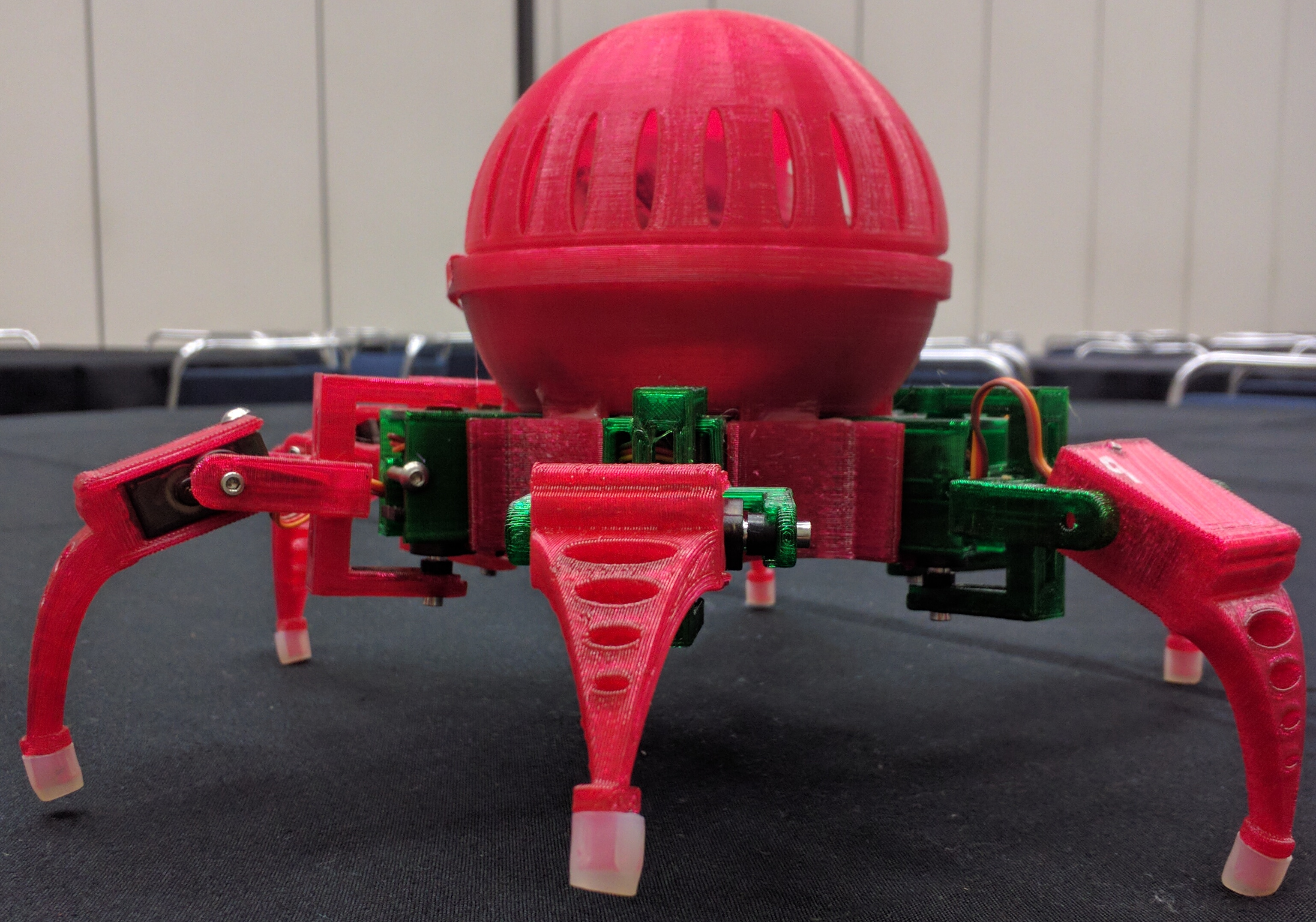
| 18:31, 1 July 2017 | Scamp-Leg-Raised.jpg (file) |  |
1.25 MB | 1 | |
| 17:38, 6 June 2017 | Spacerimage.png (file) | 197 bytes | 1 | ||
| 17:34, 6 June 2017 | ServoLegInserted.png (file) |  |
63 KB | 1 | |
| 17:34, 6 June 2017 | ServoHipInserted.png (file) |  |
74 KB | 1 | |
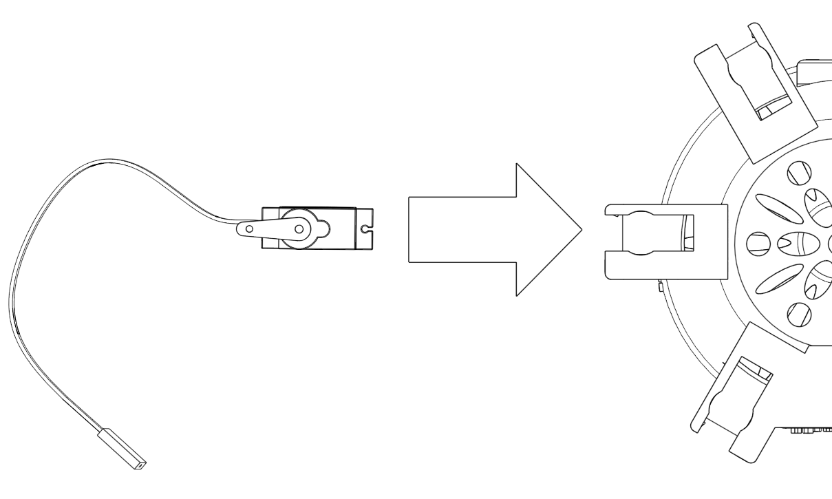
| 17:28, 6 June 2017 | ServoInsertLeg.png (file) |  |
46 KB | 1 | |
| 17:09, 6 June 2017 | ServoChassisInsert.png (file) |  |
109 KB | 1 | |
| 16:44, 6 June 2017 | VH12.jpg (file) |  |
1.99 MB | 1 | |
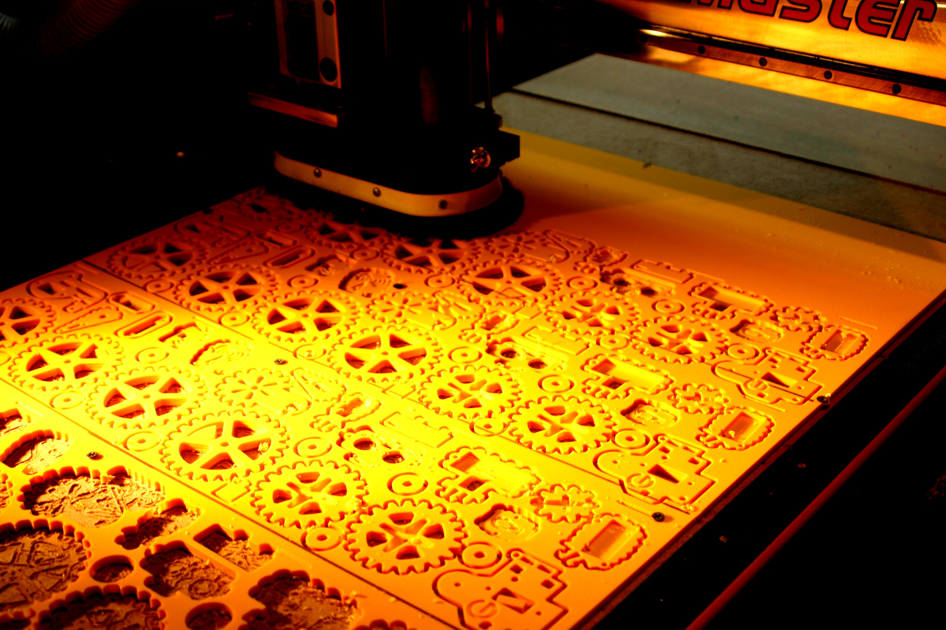
| 04:37, 10 July 2015 | Mimsy-CNC-Router-Gears.JPG (file) |  |
1.75 MB | CNC router cutting Mimsy yellow parts in the Vorpal Robotics LLC workshop. | 1 |
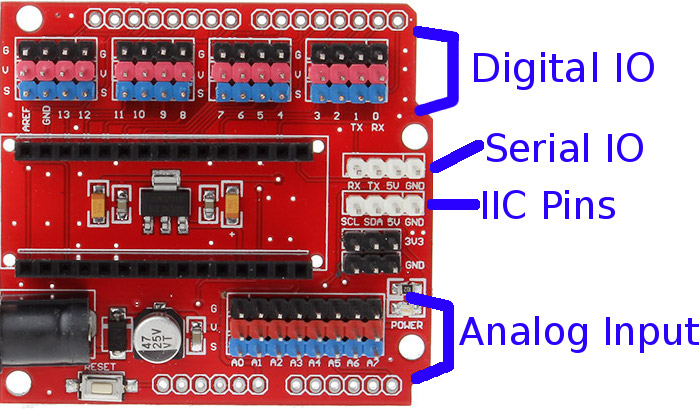
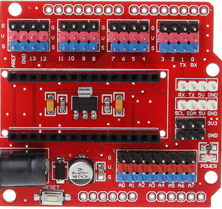
| 00:28, 10 July 2015 | Funduino-image-annotated.jpg (file) |  |
126 KB | Annotated funduino nano io shield. | 1 |
| 19:00, 9 July 2015 | Funduino-image.jpg (file) |  |
99 KB | Funduino IO Shield is used by Mimsy v1.1 | 1 |
| 18:59, 9 July 2015 | Mimsy-build-fig-42.jpg (file) |  |
459 KB | Mimsy build figure 42. | 1 |
| 18:58, 9 July 2015 | Mimsy-build-fig-41.jpg (file) |  |
492 KB | Mimsy build figure 41. | 1 |
| 18:58, 9 July 2015 | Mimsy-build-fig-40.jpg (file) |  |
676 KB | Mimsy build figure 40. | 1 |
| 18:57, 9 July 2015 | Mimsy-build-fig-39.jpg (file) |  |
984 KB | Mimsy build figure 39. | 1 |
| 18:50, 9 July 2015 | Mimsy-build-fig-38.jpg (file) |  |
862 KB | Mimsy build figure 38. | 1 |
| 18:48, 9 July 2015 | Mimsy-build-fig-37.jpg (file) |  |
302 KB | 2 | |
| 18:31, 9 July 2015 | Mimsy-build-fig-36.jpg (file) |  |
1.2 MB | Mimsy build figure 36. | 1 |
| 17:47, 9 July 2015 | Mimsy-build-fig-35.jpg (file) |  |
1.15 MB | Mimsy build figure 35. | 1 |
| 17:46, 9 July 2015 | Mimsy-build-fig-34.jpg (file) |  |
1.22 MB | Mimsy build figure 34. | 1 |
| 17:44, 9 July 2015 | Mimsy-build-fig-33.jpg (file) |  |
1.39 MB | Mimsy build figure 33. | 1 |
| 17:43, 9 July 2015 | Mimsy-build-fig-32.jpg (file) |  |
822 KB | Mimsy build figure 32. | 1 |
| 17:30, 9 July 2015 | Mimsy-build-fig-31.jpg (file) |  |
941 KB | Mimsy build figure 31. | 1 |
| 17:25, 9 July 2015 | Mimsy-build-fig-30.jpg (file) |  |
834 KB | Mimsy build figure 30. | 1 |
| 02:34, 30 June 2015 | Mimsy-build-fig-29.jpg (file) |  |
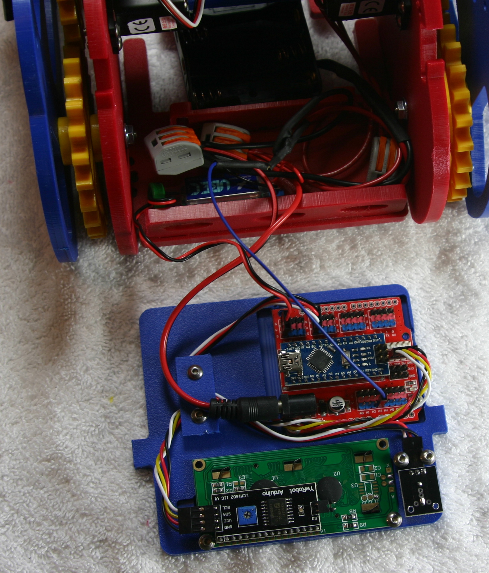
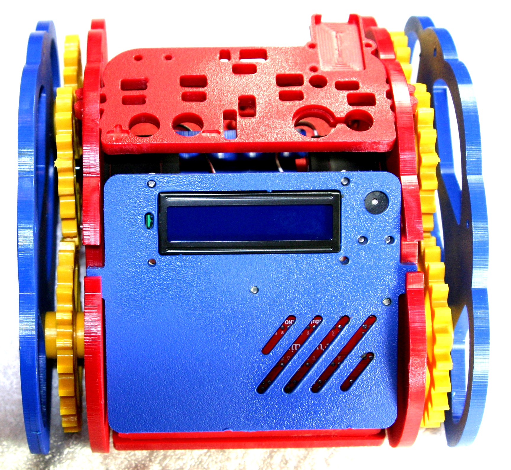
1.41 MB | Mimsy Build figure 29. The console fits in the two slots on the rear of Mimsy as shown. | 1 |
| 02:29, 30 June 2015 | Mimsy-build-fig-28.jpg (file) |  |
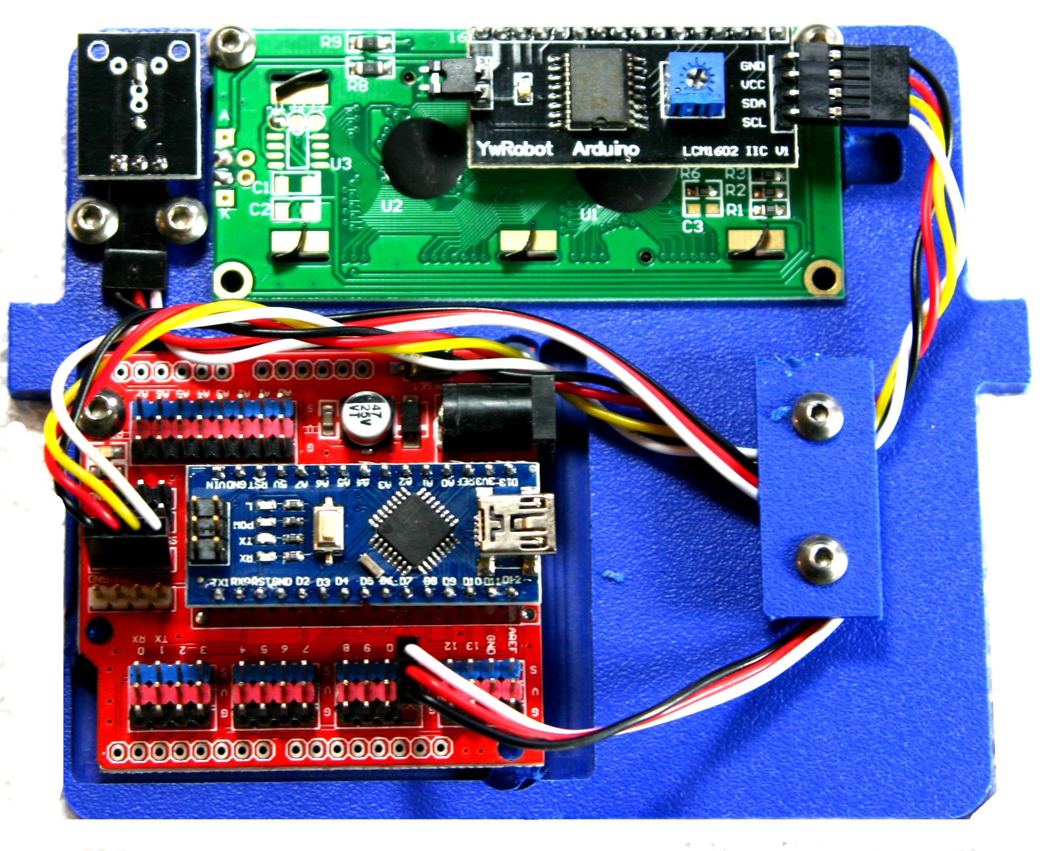
1.48 MB | Mimsy Build figure 28. Route the cables as shown and use the console wire plate and two 3/8" screws to hold them in place. | 1 |
| 02:15, 30 June 2015 | Mimsy-build-fig-27.jpg (file) |  |
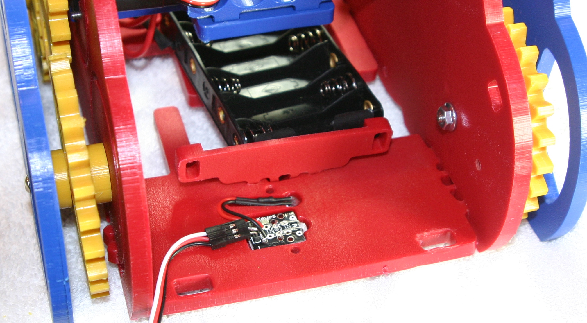
1.38 MB | Mimsy Build figure 27. Install the buzzer using two 3/8" screws, do not overtighten. Connect the LCD cable as shown with the black wire at the top. | 1 |
| 02:03, 30 June 2015 | Mimsy-build-fig-26.jpg (file) |  |
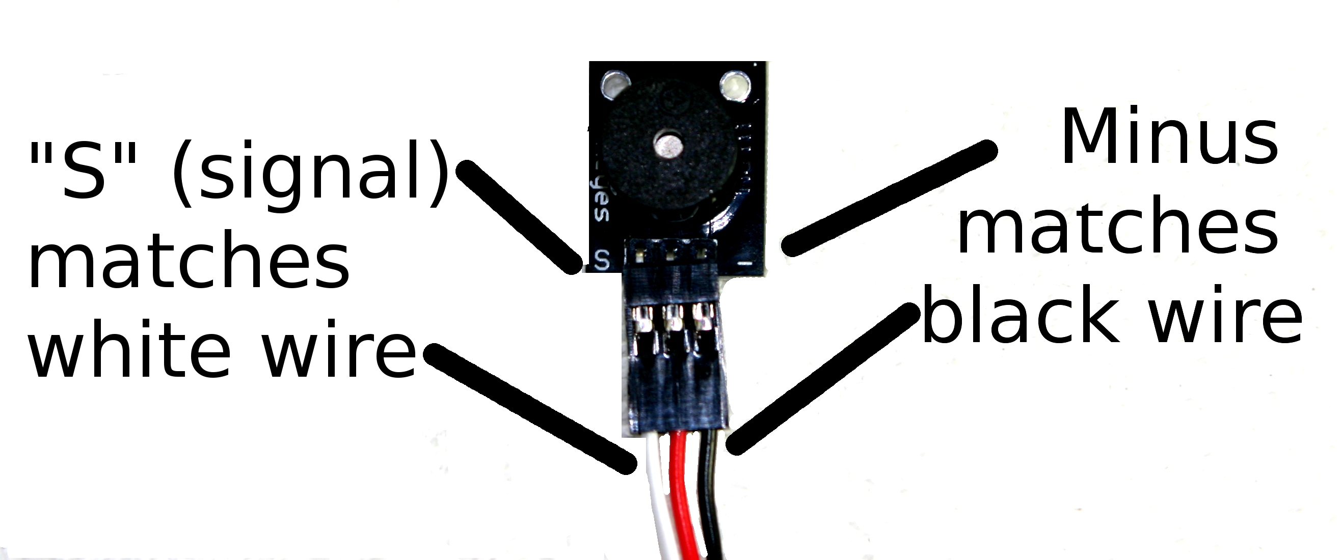
303 KB | Mimsy Build figure 26. Attaching the 10cm 3-wire cable to the buzzer. The black wire matches with the "-" marking while the white matches the "S" marking. | 1 |
| 03:05, 29 June 2015 | Mimsy-build-fig-25.jpg (file) |  |
1.36 MB | Mimsy Build figure 25. The LCD is secured with two screws at the top of the console bezel. | 1 |
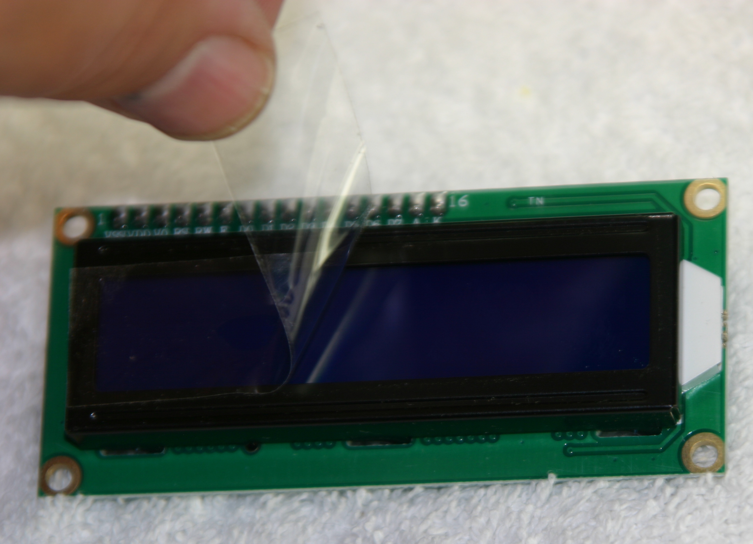
| 02:59, 29 June 2015 | Mimsy-build-fig-24.jpg (file) |  |
965 KB | Mimsy Build figure 24. Remove the protective plastic from the LCD before installing. | 1 |
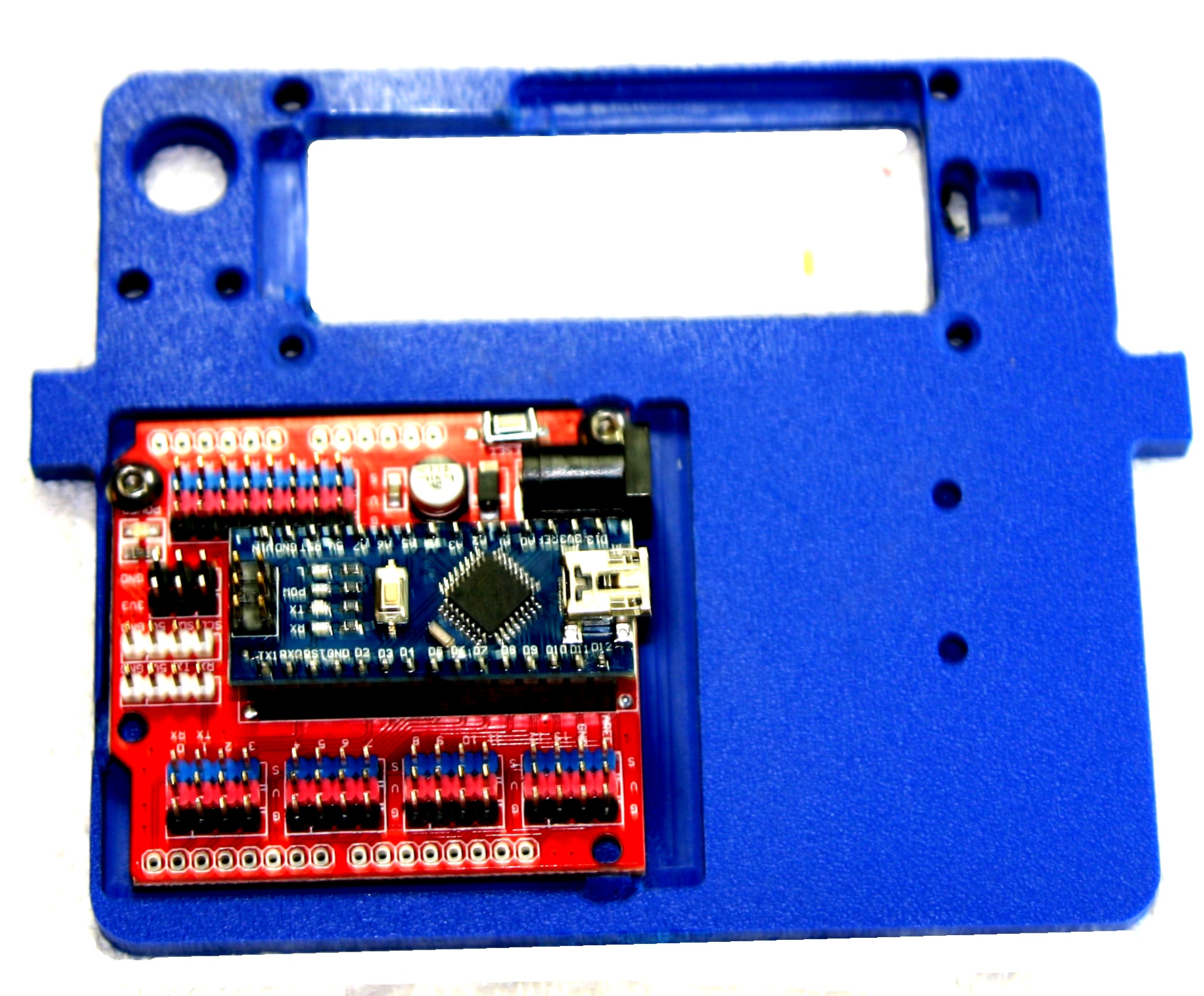
| 02:53, 29 June 2015 | Mimsy-build-fig-23.jpg (file) |  |
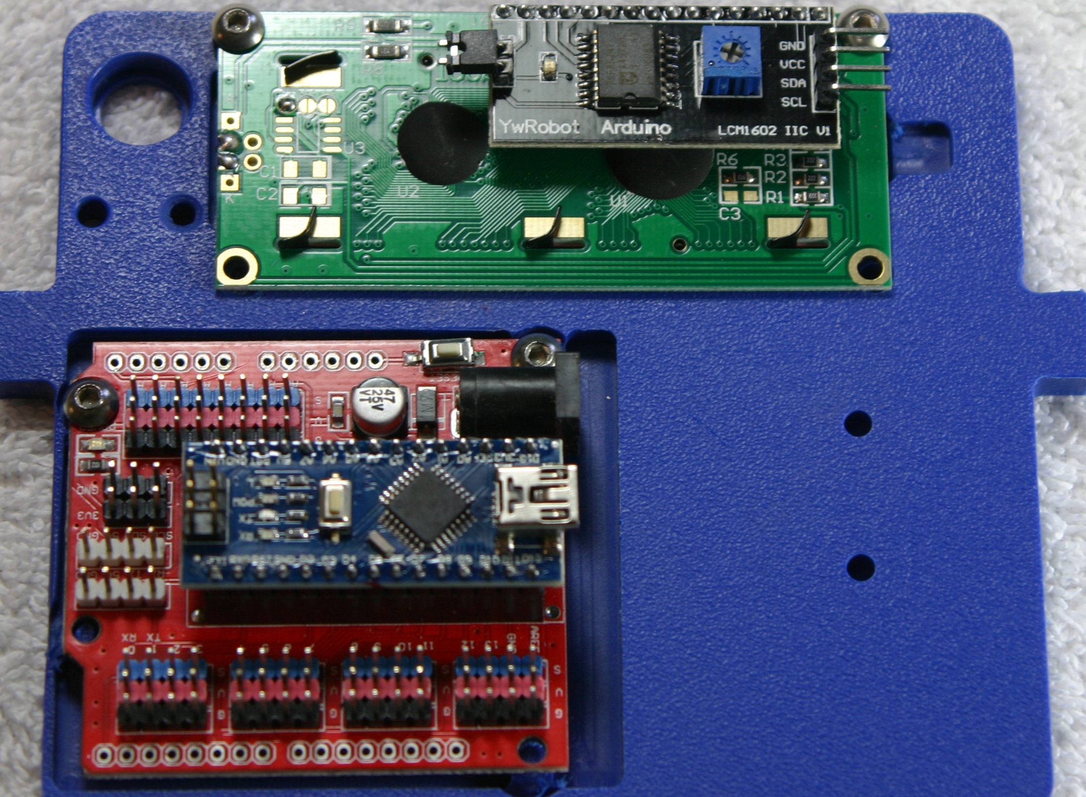
892 KB | Mimsy Build figure 23. Installation of Arduino Nano and IO shield on console. | 1 |
| 02:42, 29 June 2015 | Mimsy-build-fig-22.jpg (file) |  |
1.33 MB | Mimsy Build figure 22. Parts needed to assemble control panel. | 1 |
| 02:28, 29 June 2015 | Mimsy-build-fig-21.jpg (file) |  |
1.37 MB | Mimsy Build figure 21. The front floor is shown with fence installed. | 1 |
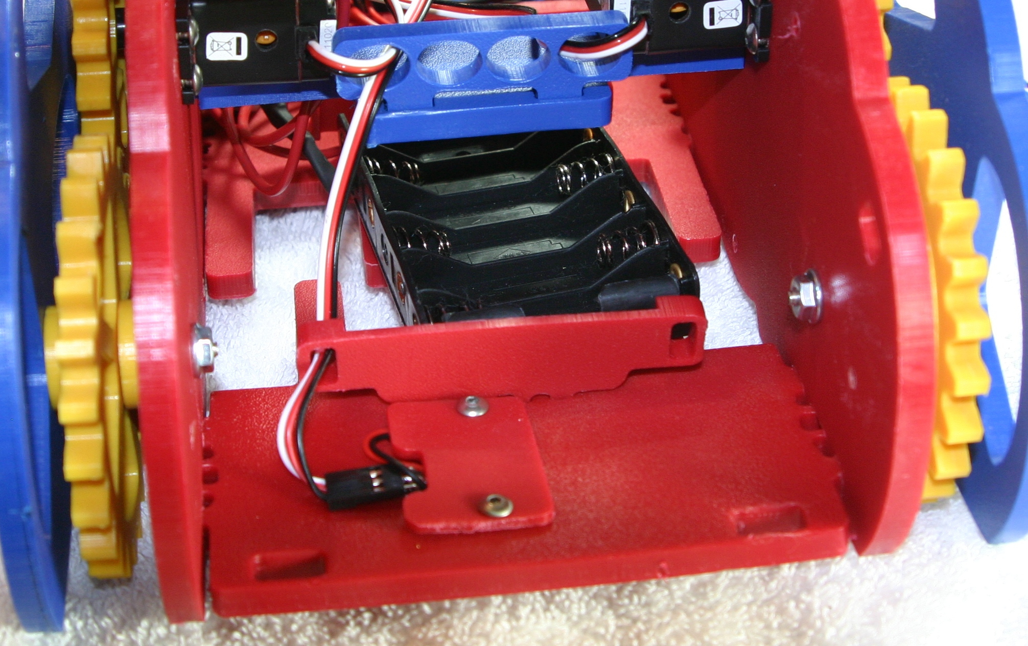
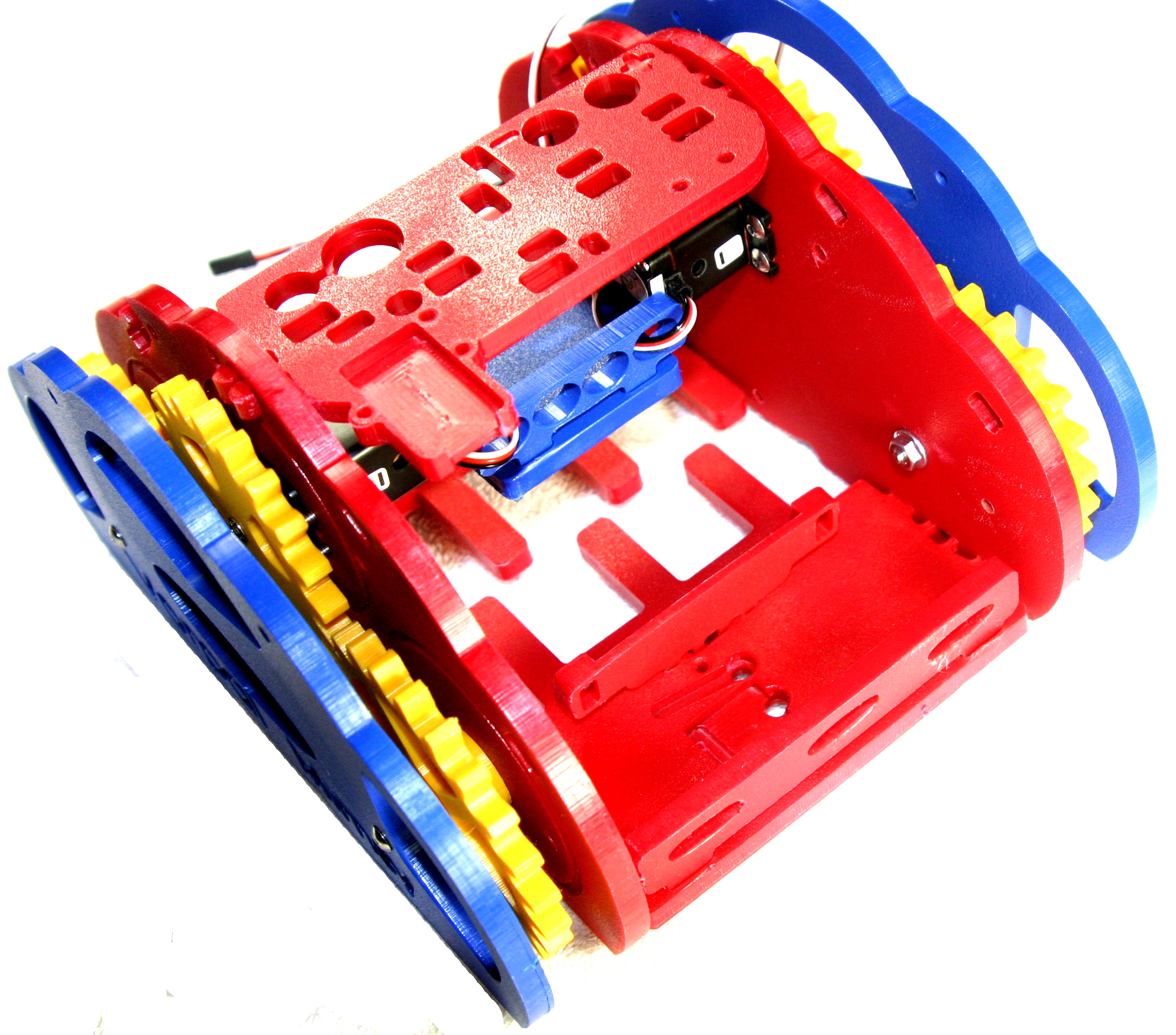
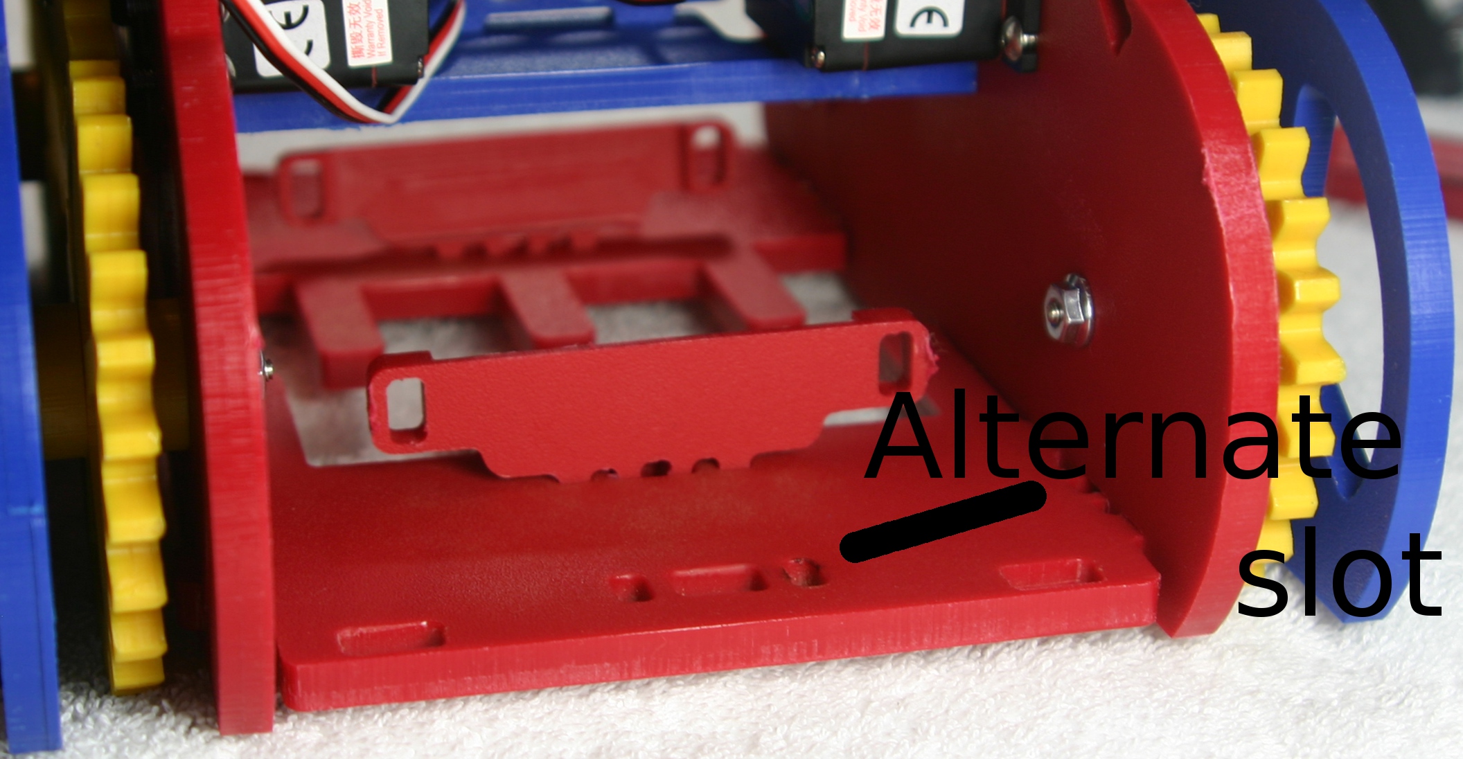
| 02:24, 29 June 2015 | Mimsy-build-fig-20.jpg (file) |  |
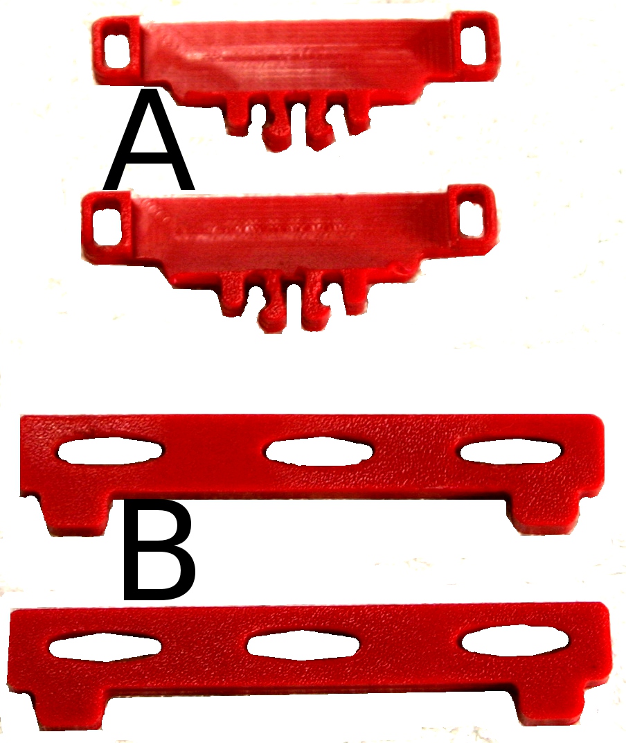
652 KB | Mimsy Build figure 20. Installation of battery brackets. Alternate position is for alternative batteries such as 7.2 volt NIMH RC batteries. | 1 |
| 02:23, 29 June 2015 | Mimsy-build-fig-19.jpg (file) |  |
273 KB | Mimys Build figure 19. Parts needed to install battery brackets and fences. | 1 |
| 01:51, 29 June 2015 | Mimsy-build-fig-18.jpg (file) |  |
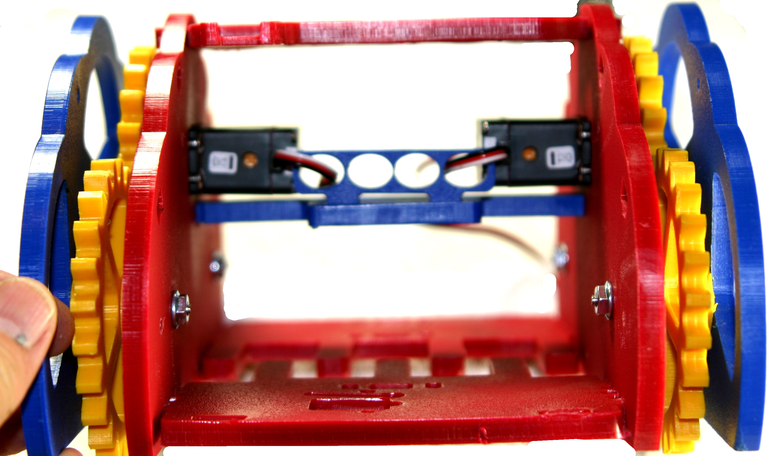
1.27 MB | Mimsy Build figure 18. Front view of chassis with servo wires routed to the rear. | 1 |
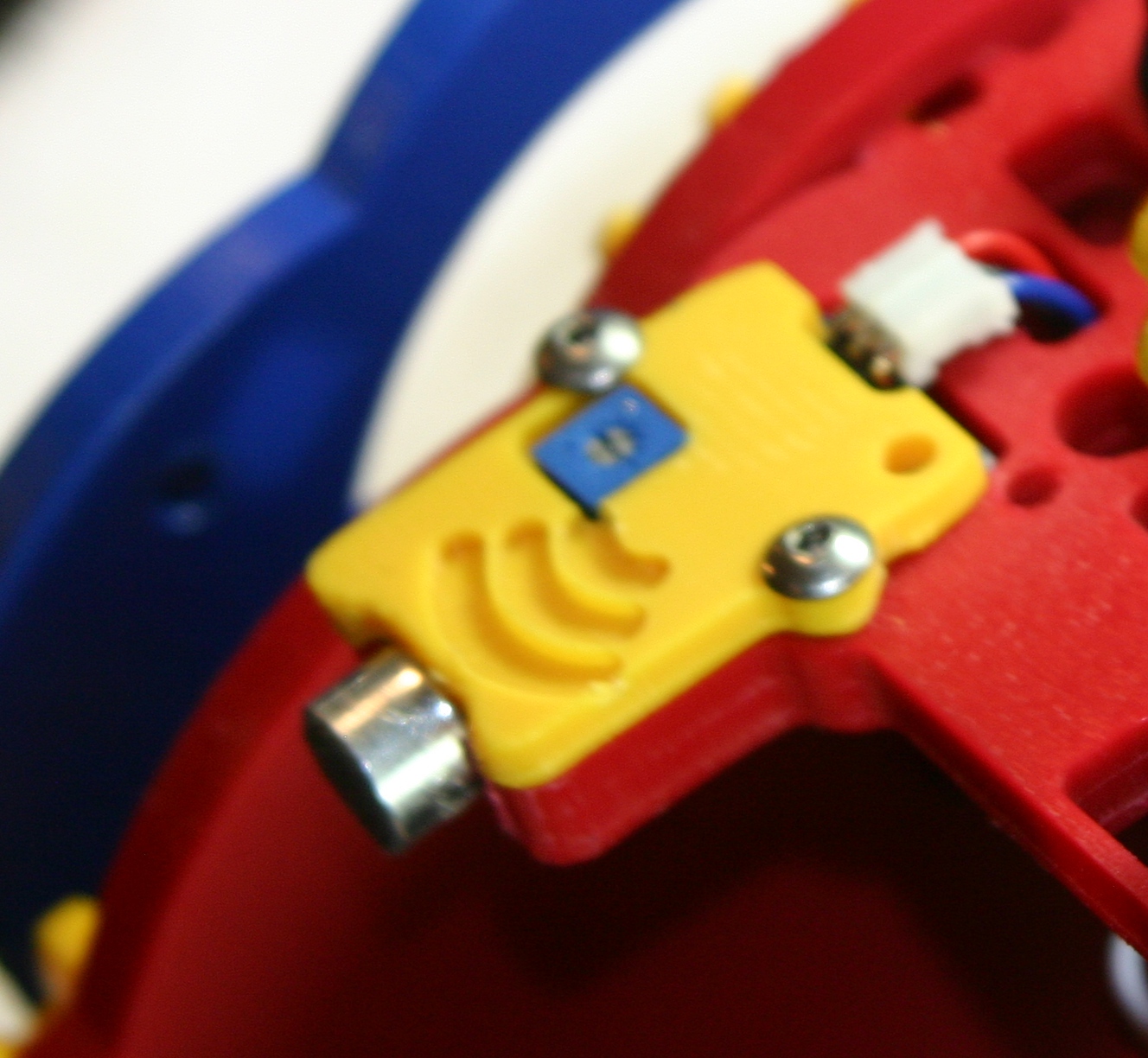
| 01:44, 29 June 2015 | Mimsy-build-fig-17.jpg (file) |  |
1.09 MB | Mimsy Build figure 17: using the same locking tab and slot system, take the sensor bar and align and press in first one side and then the other. | 1 |
| 01:35, 29 June 2015 | Mimsy-build-fig-16.jpg (file) |  |
800 KB | Mimsy Build figure 16. Insert the cross bar wire guide in the cross bar and firmly press. | 1 |