File list
From Vorpal Robotics Wiki
This special page shows all uploaded files.
| Date | Name | Thumbnail | Size | User | Description | Versions |
|---|---|---|---|---|---|---|
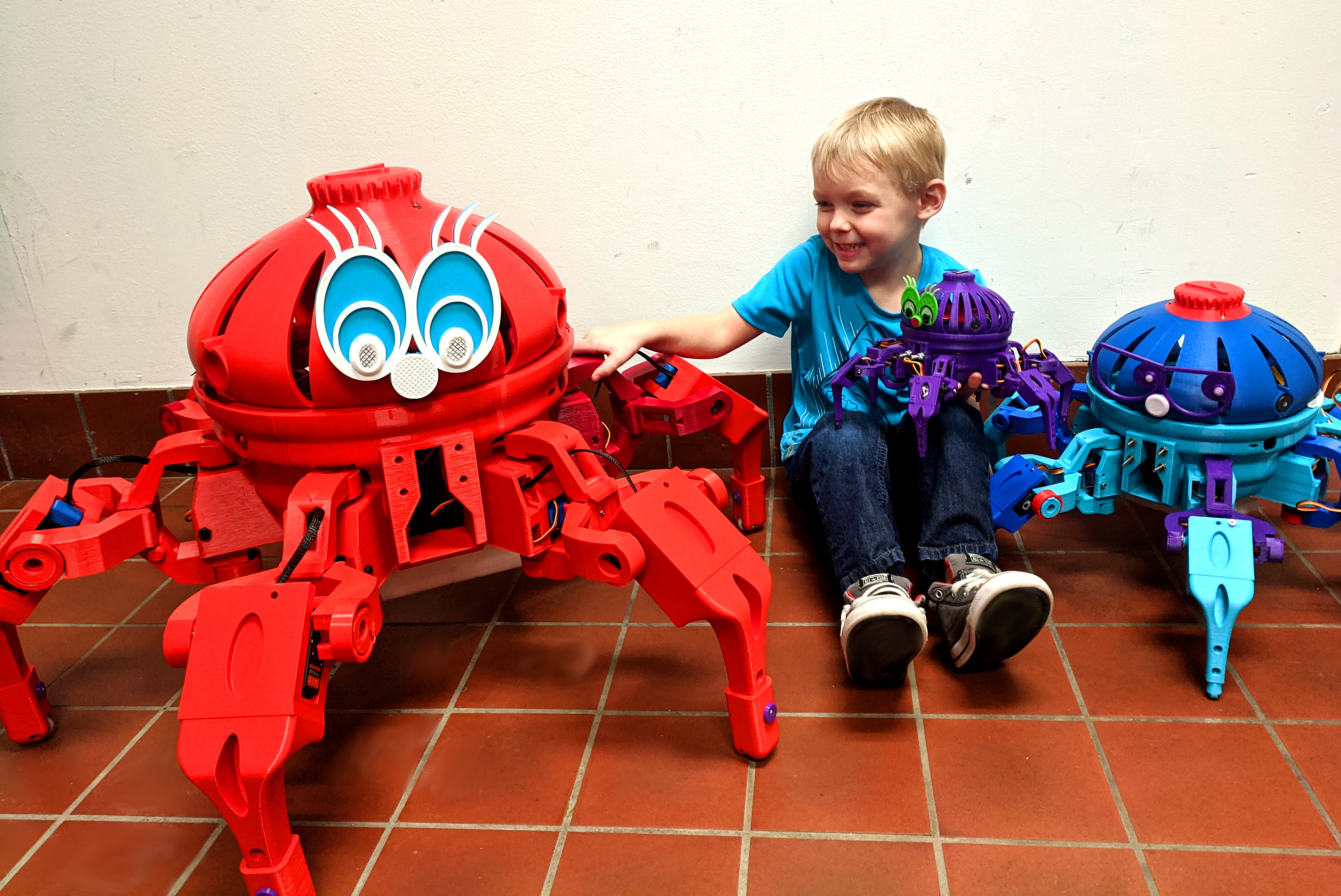
| 16:48, 28 January 2020 | Child+Giga+Mega+Hexa.jpg (file) |  |
4.26 MB | Vorpalwiki | 1 | |
| 14:16, 20 March 2020 | Covid-Bracelet-Top-View-Labelled-band.jpg (file) |  |
3.51 MB | Vorpalwiki | 1 | |
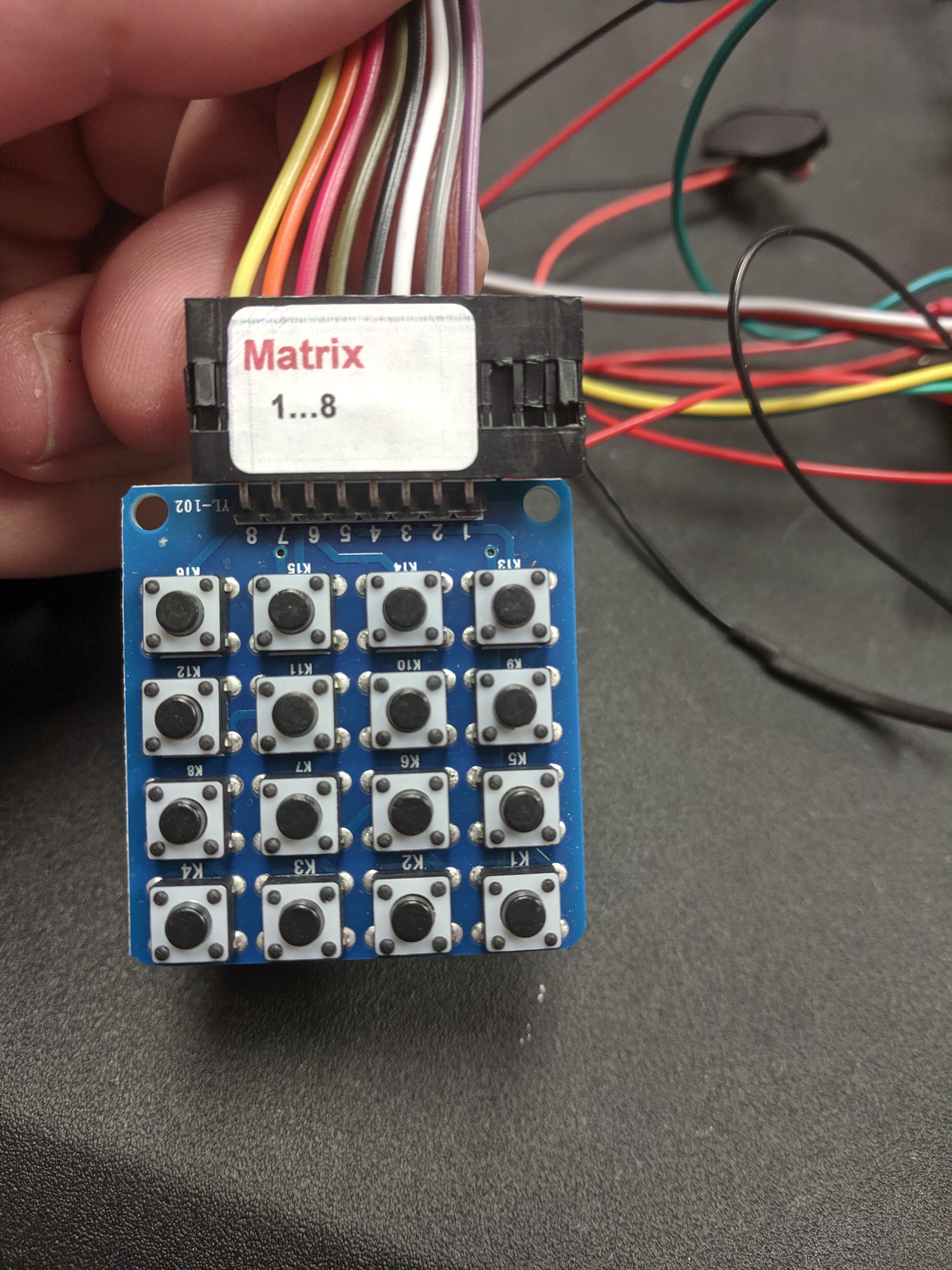
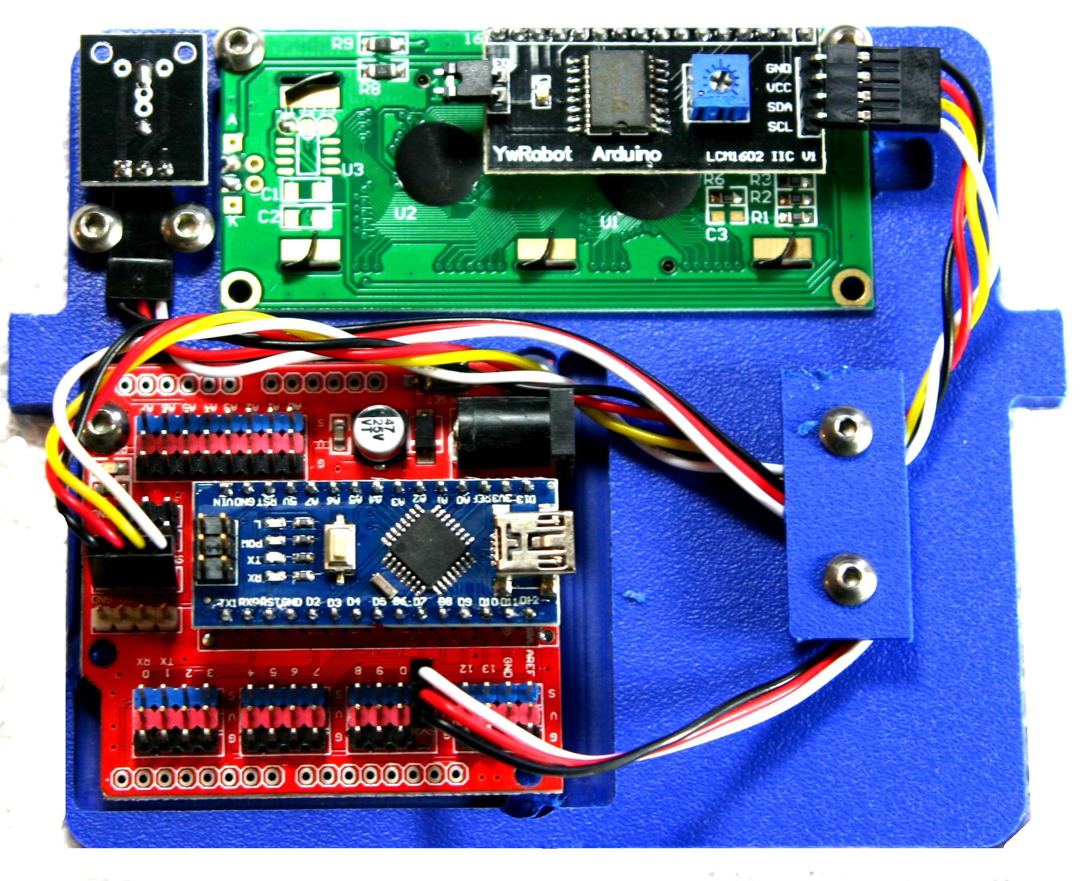
| 14:08, 22 October 2019 | MATRIX-1-8.JPG (file) |  |
3.47 MB | Vorpalwiki | 1 | |
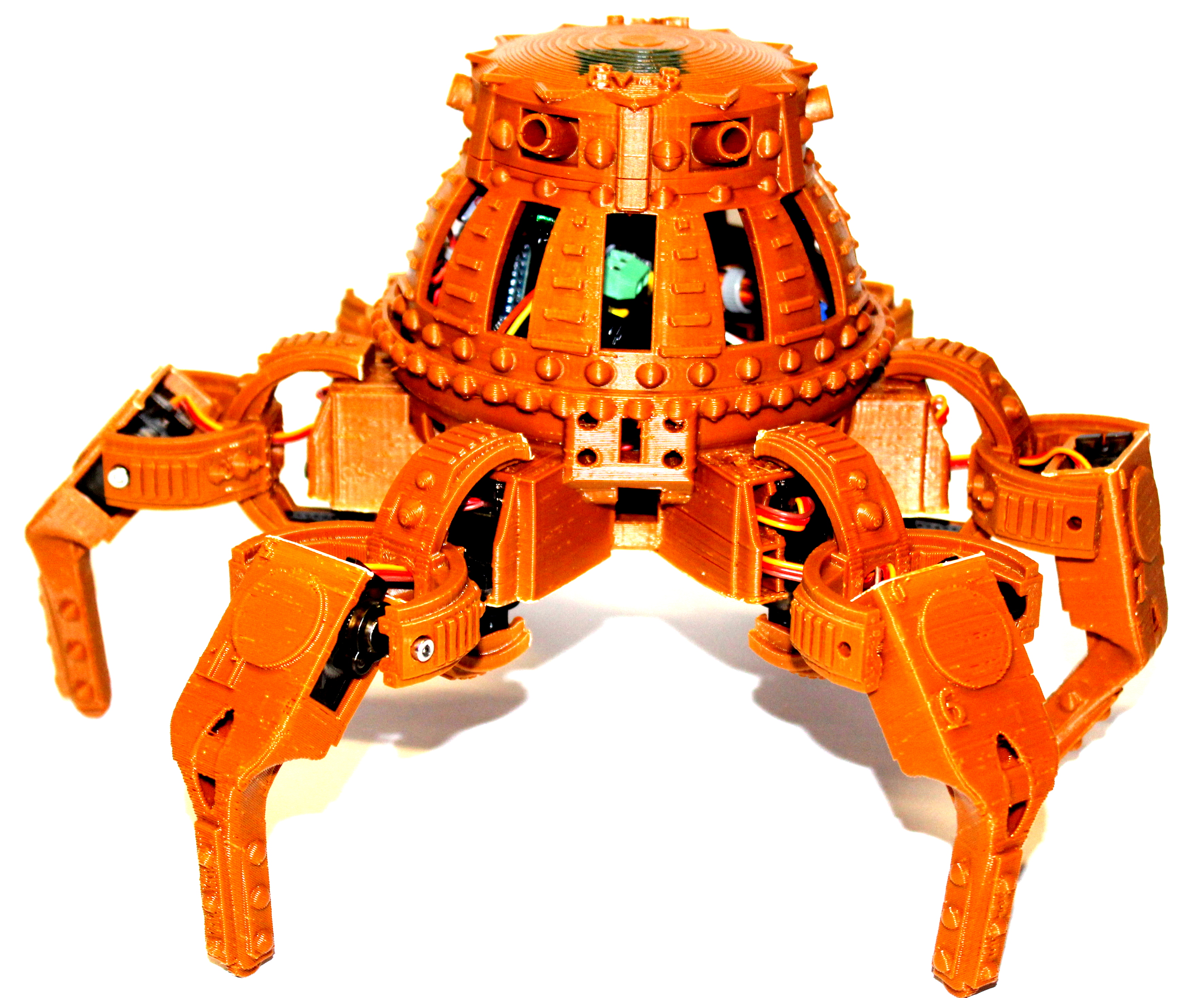
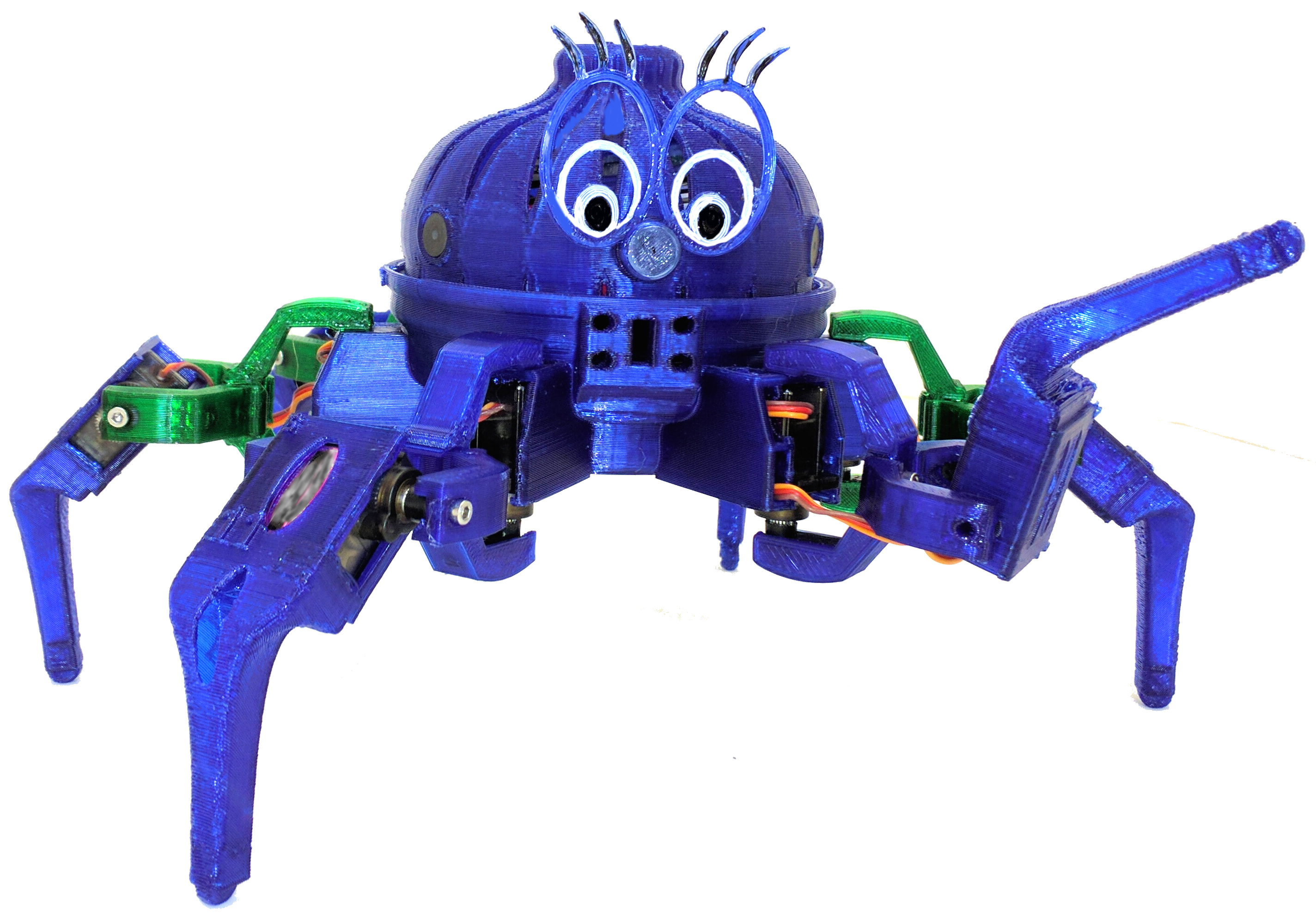
| 16:09, 21 August 2017 | Evan-Gagnon-Hexapod-Skin.JPG (file) |  |
3.01 MB | Vorpalwiki | Evan Gagnon of Green, New Jersey designed this medieval-looking hexapod using the Vorpal Hexapod open source STL files as a base. | 1 |
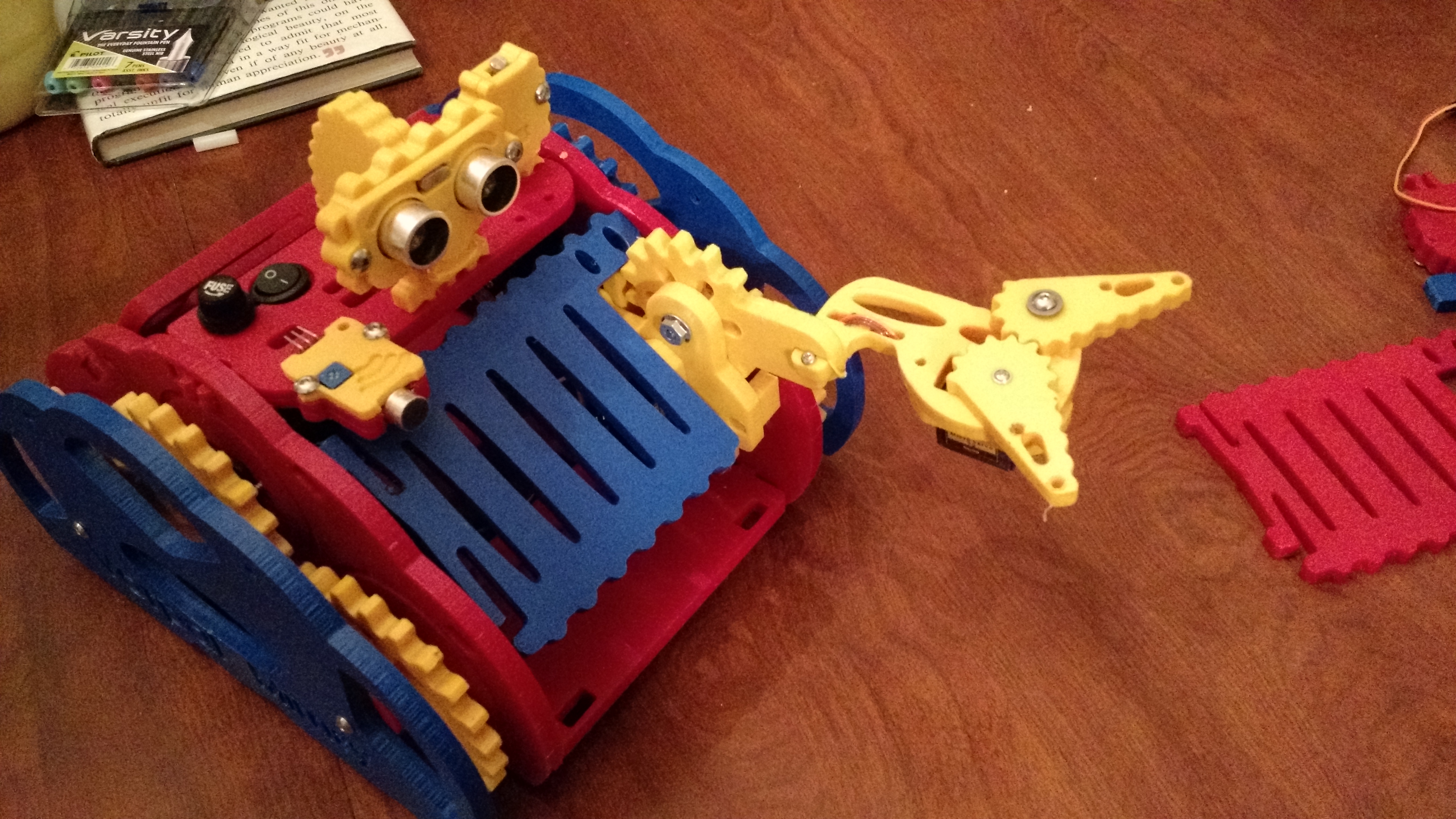
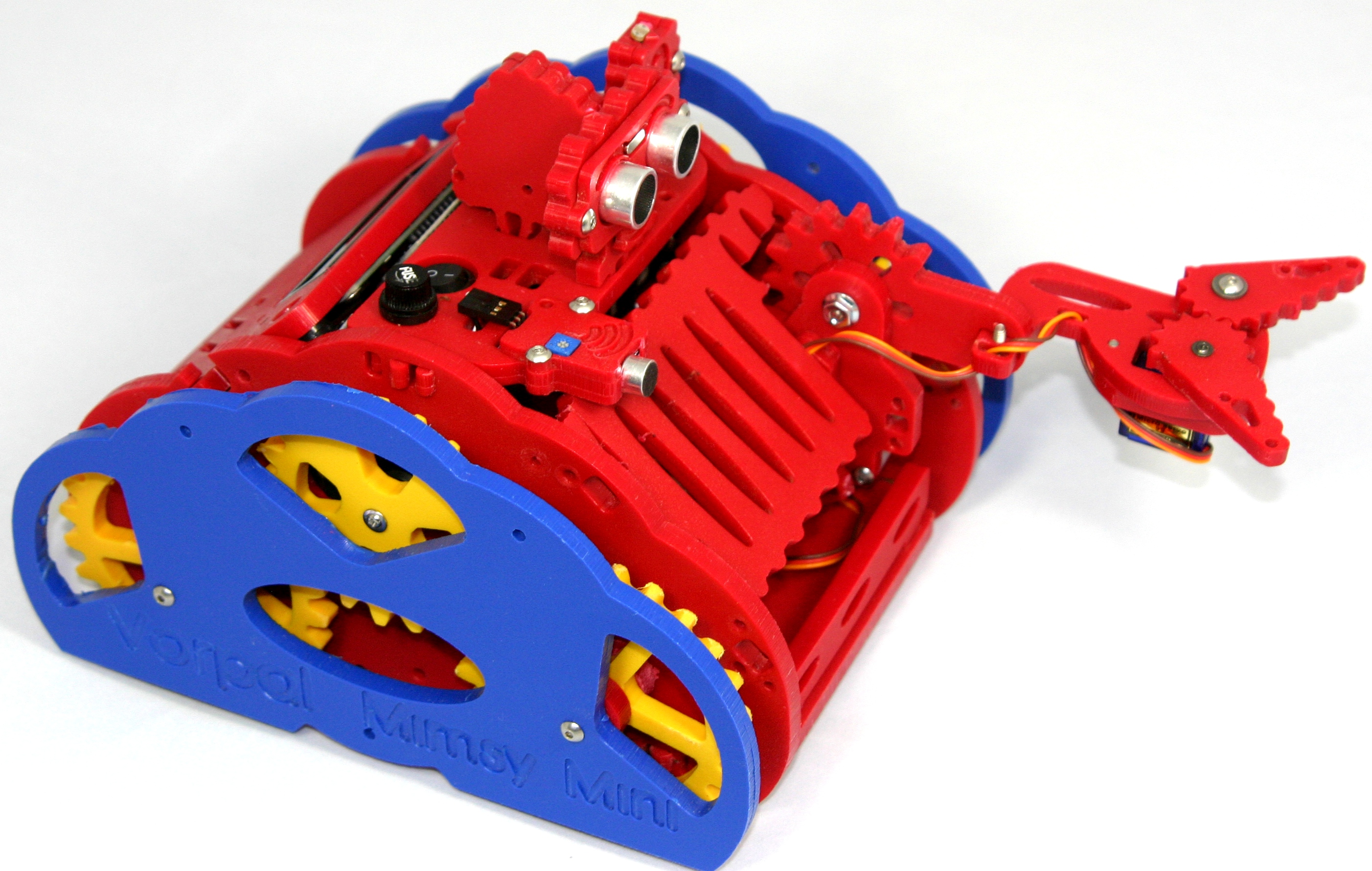
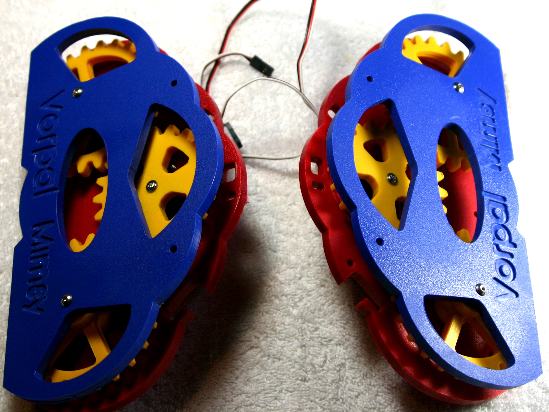
| 17:10, 22 June 2015 | 05-Mimsy-yellow-arm-yellow-sensor-blue-grill.jpg (file) |  |
2.94 MB | Vorpalwiki | Vorpal Mimsy with yellow and blue theme | 1 |
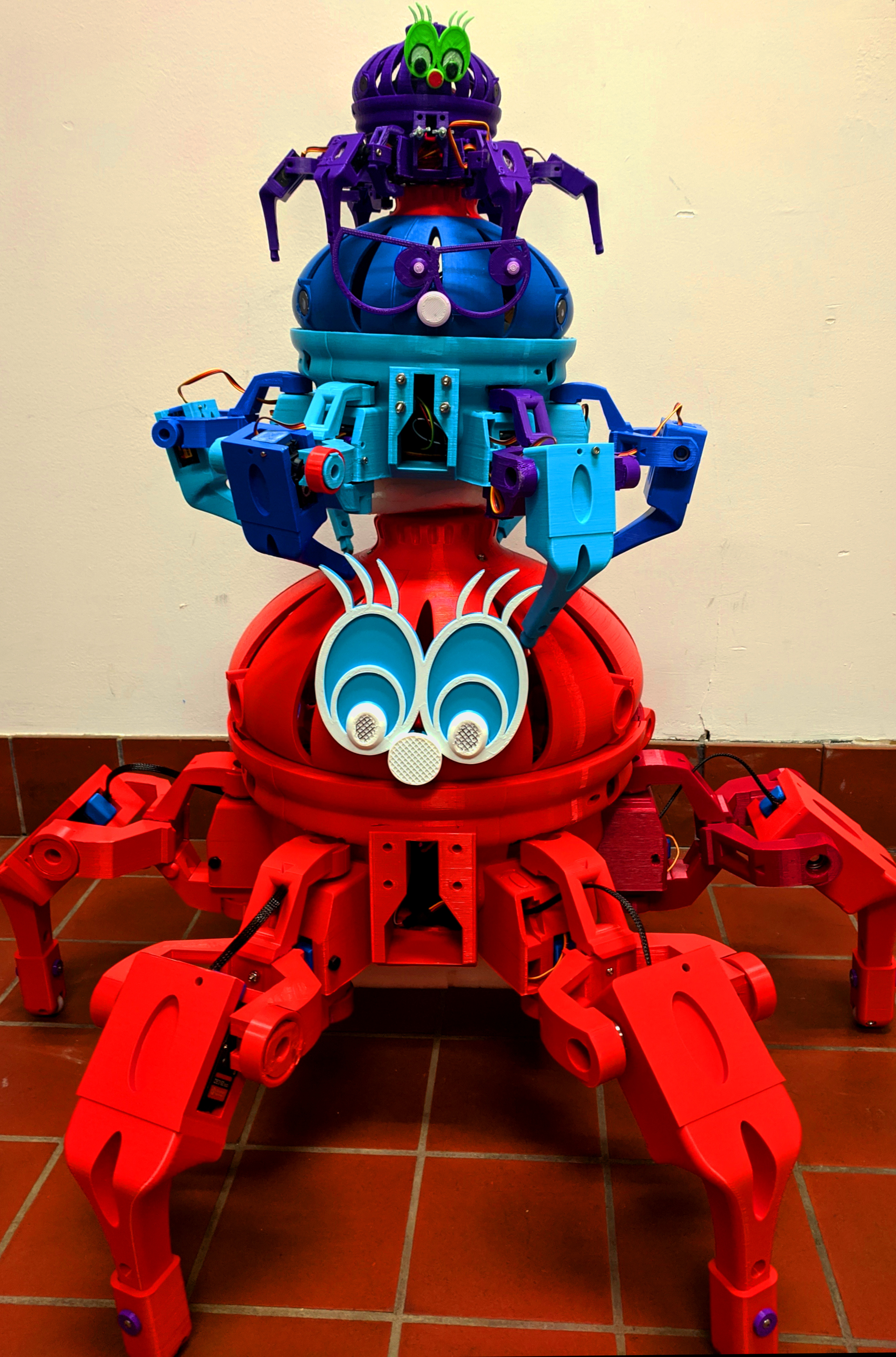
| 16:50, 28 January 2020 | Giga-Mega-Hexa-Stacked.jpg (file) |  |
2.88 MB | Vorpalwiki | 1 | |
| 20:04, 13 November 2019 | Robot-Foam-Installation.JPG (file) |  |
2.84 MB | Vorpalwiki | 1 | |
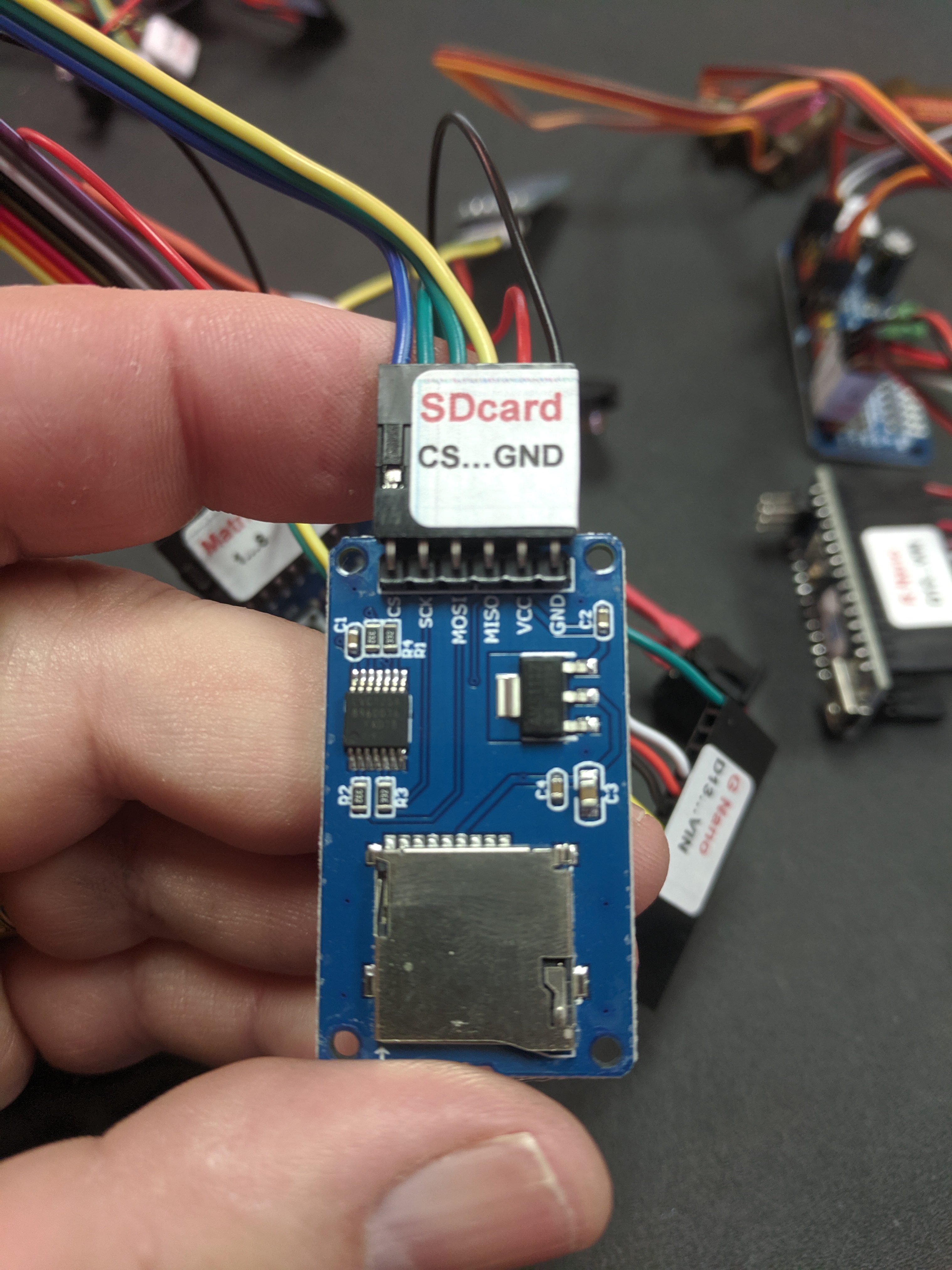
| 14:12, 22 October 2019 | SDCARD-CS-GND.JPG (file) |  |
2.62 MB | Vorpalwiki | 1 | |
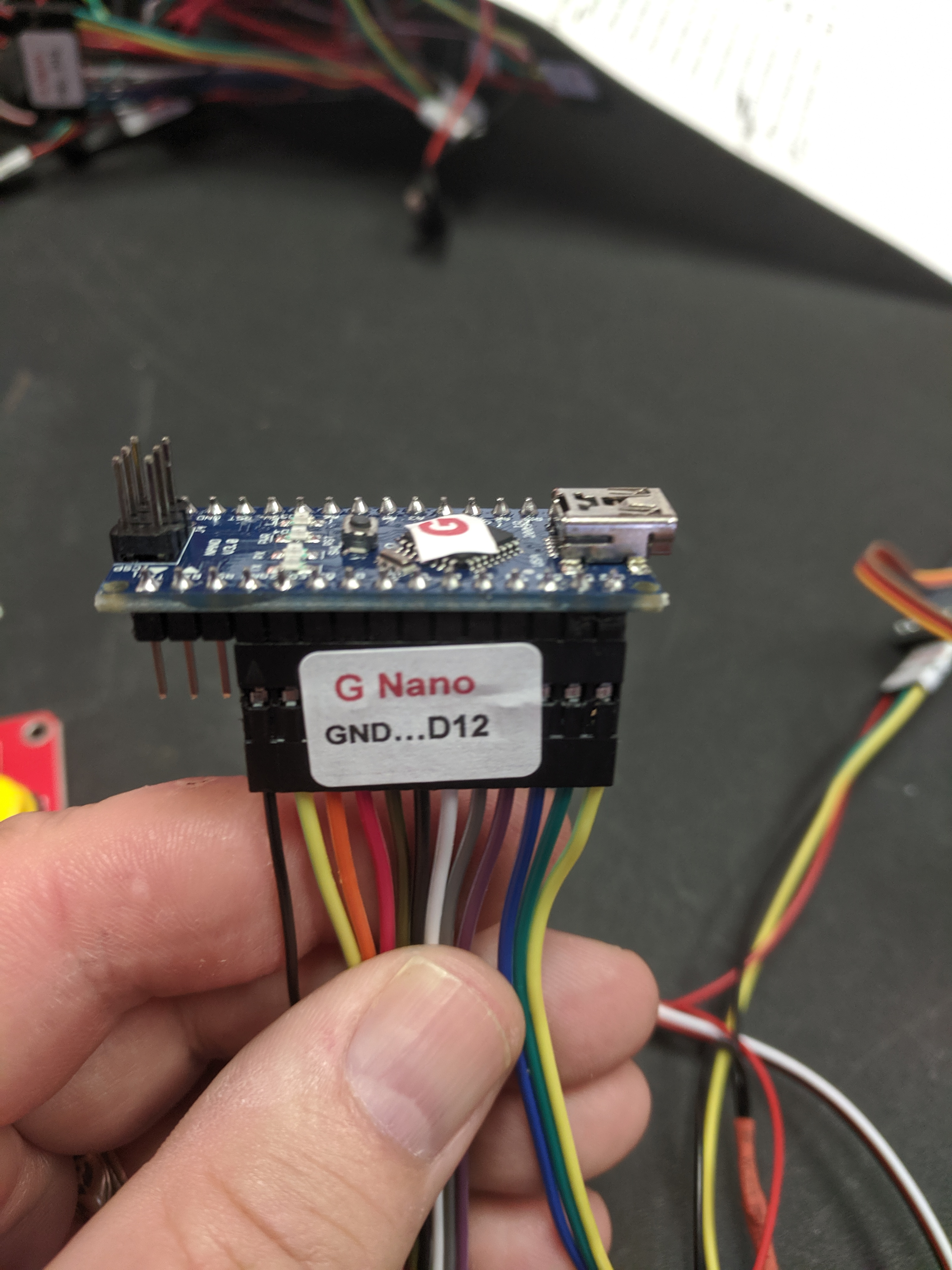
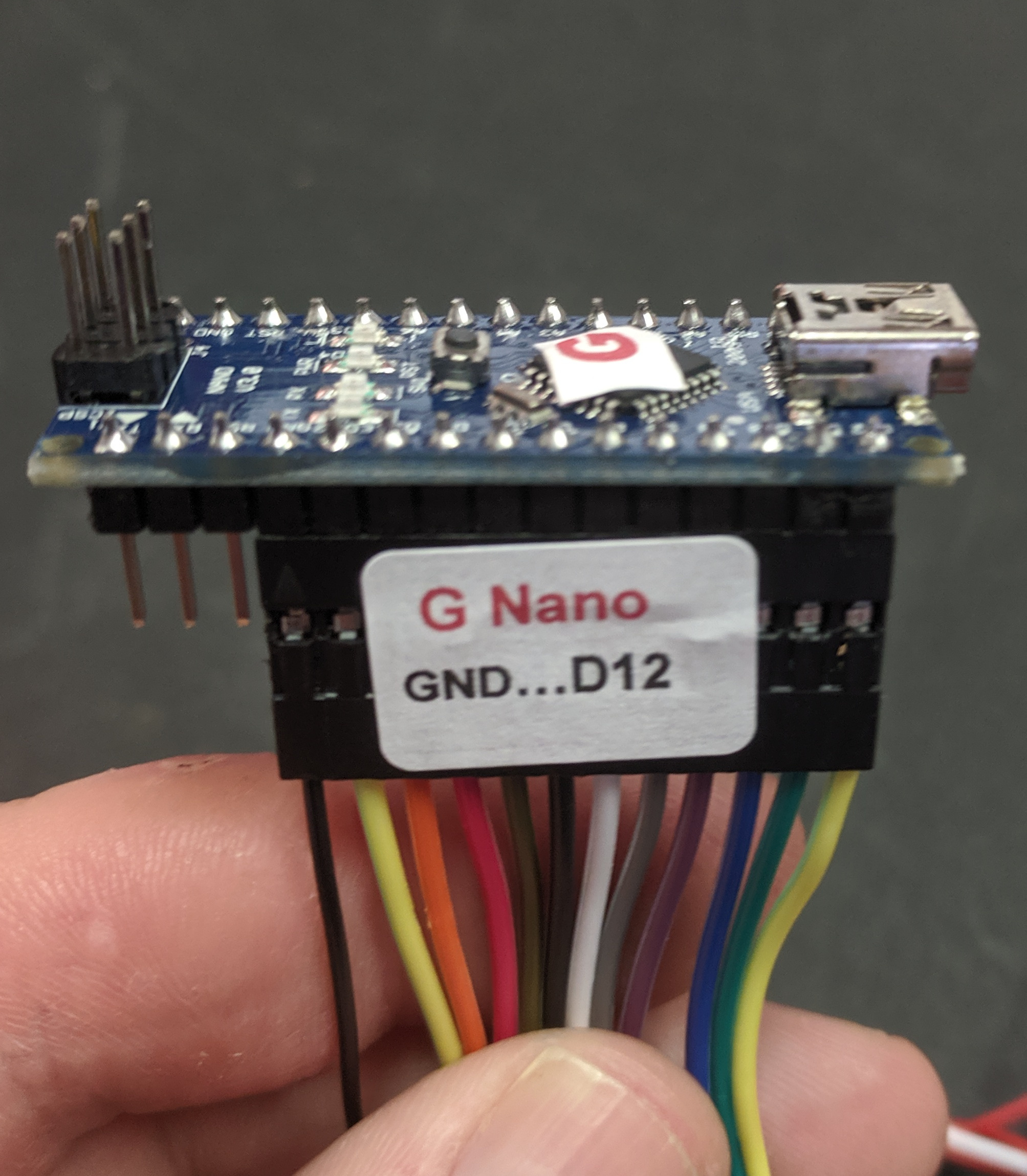
| 14:06, 22 October 2019 | GNANO-GND-D12.JPG (file) |  |
2.5 MB | Vorpalwiki | 1 | |
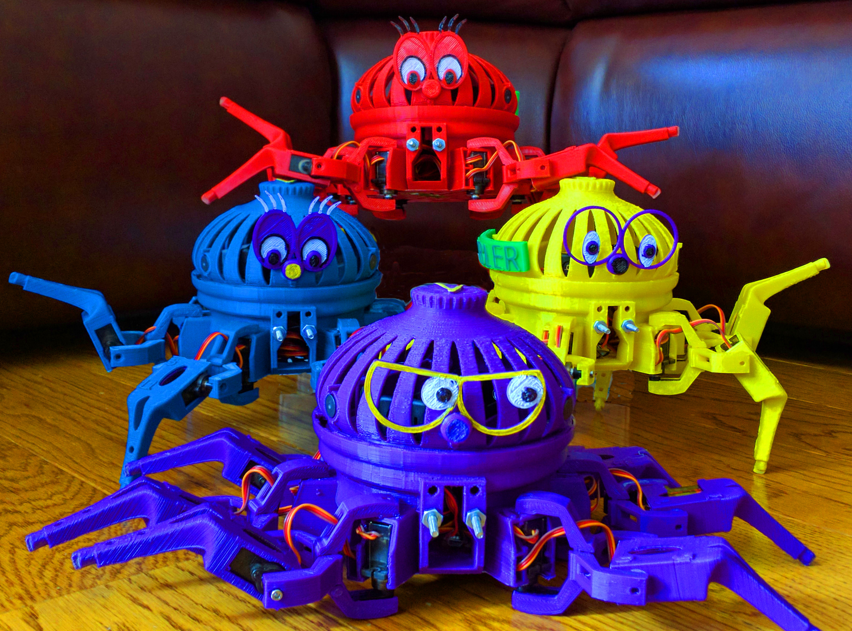
| 04:37, 18 October 2017 | Vorpal-Hexapods-Pyramid-DPR.jpg (file) |  |
2.47 MB | Vorpalwiki | 1 | |
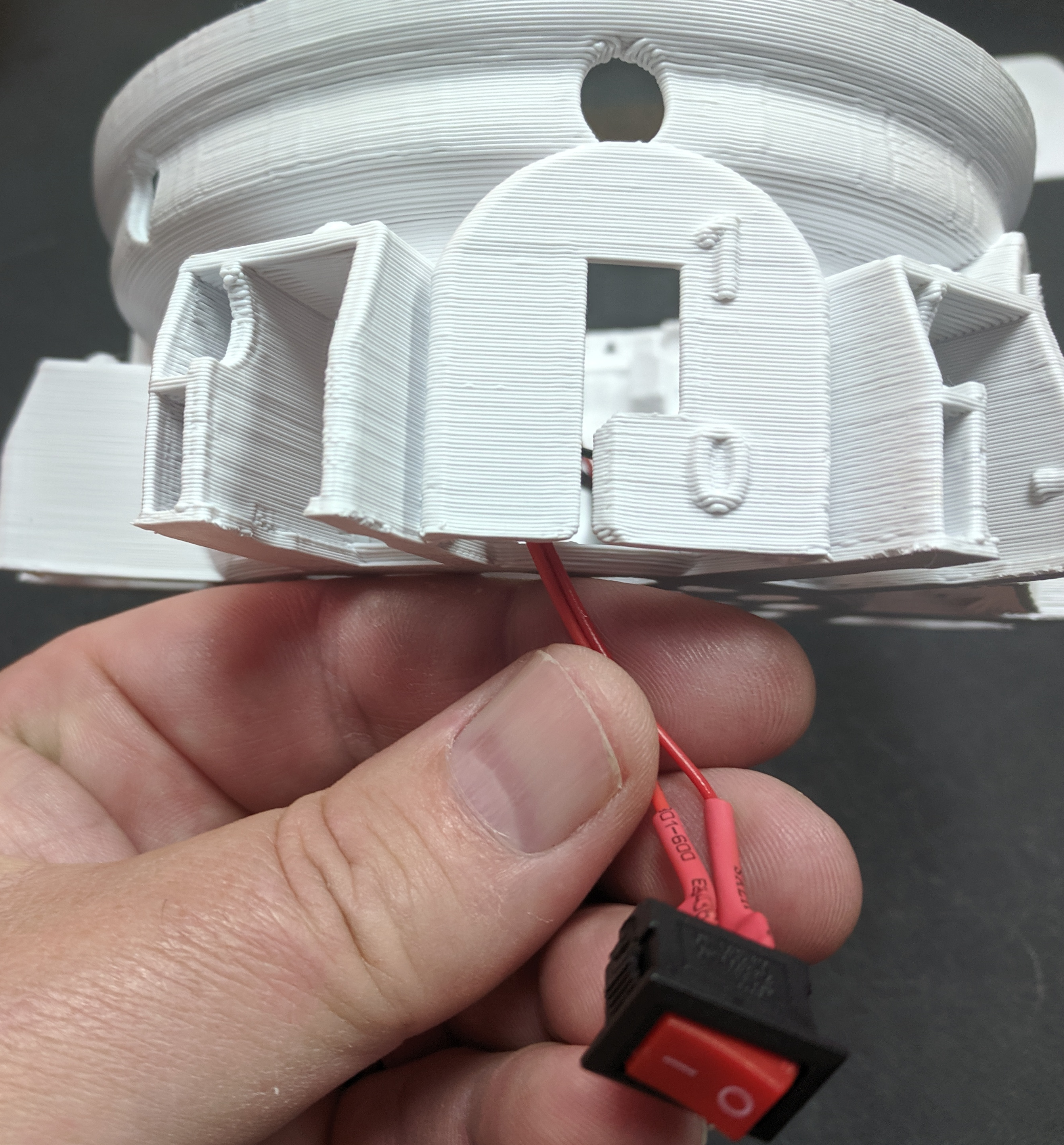
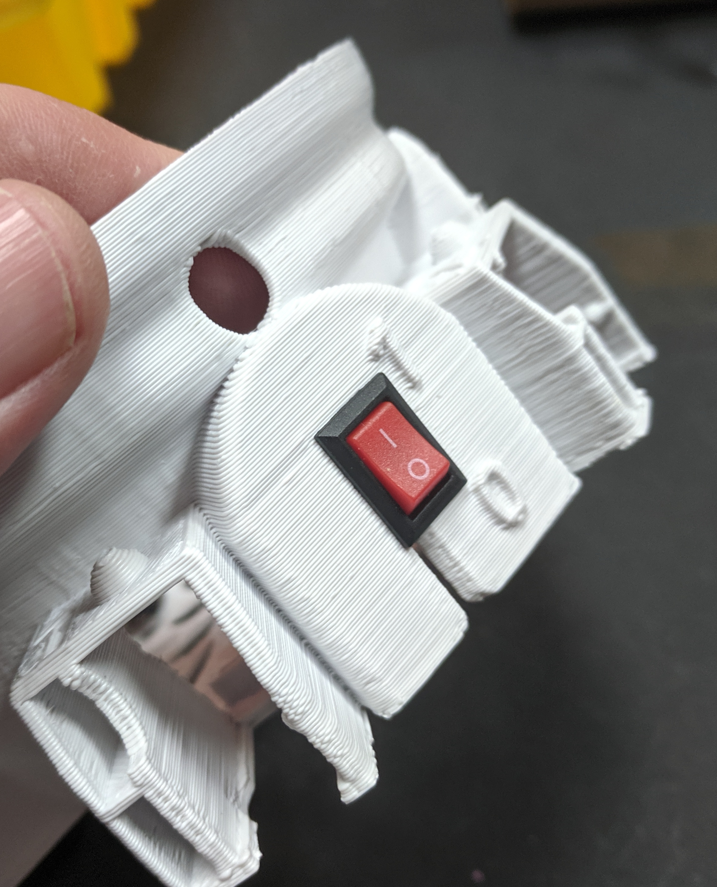
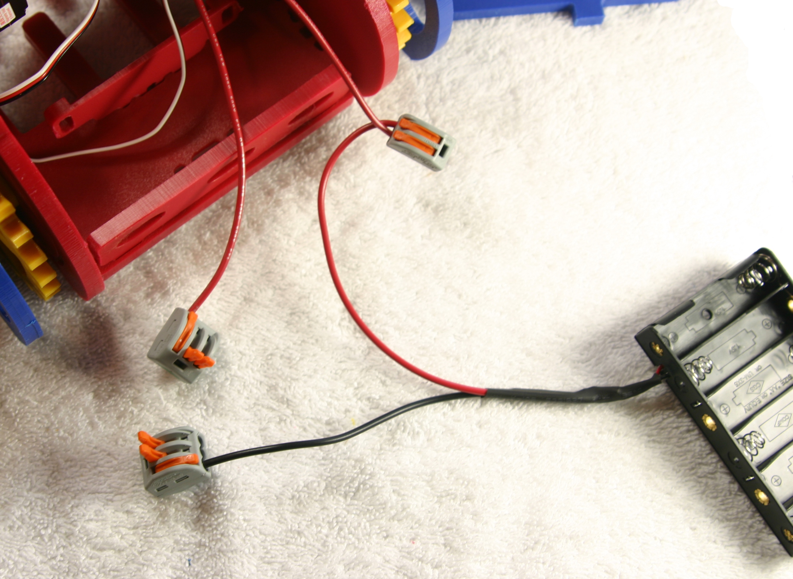
| 00:44, 20 October 2019 | NewSwitchInstall-Step1.jpg (file) |  |
2.08 MB | Vorpalwiki | 1 | |
| 16:44, 6 June 2017 | VH12.jpg (file) |  |
1.99 MB | Vorpalwiki | 1 | |
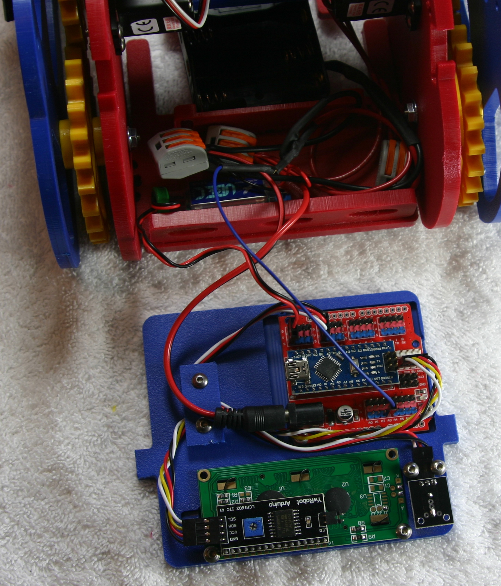
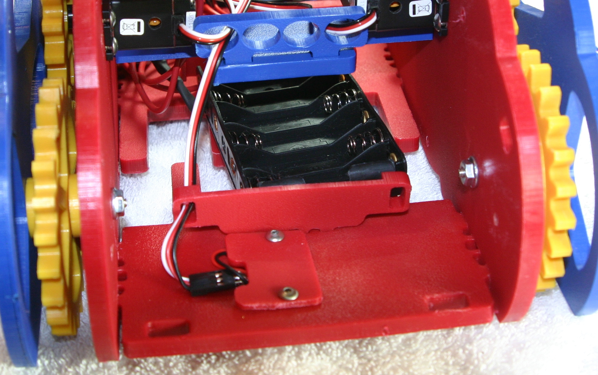
| 13:34, 19 January 2018 | Base-Battery-Drawer-Open.jpg (file) |  |
1.98 MB | Vorpalwiki | 1 | |
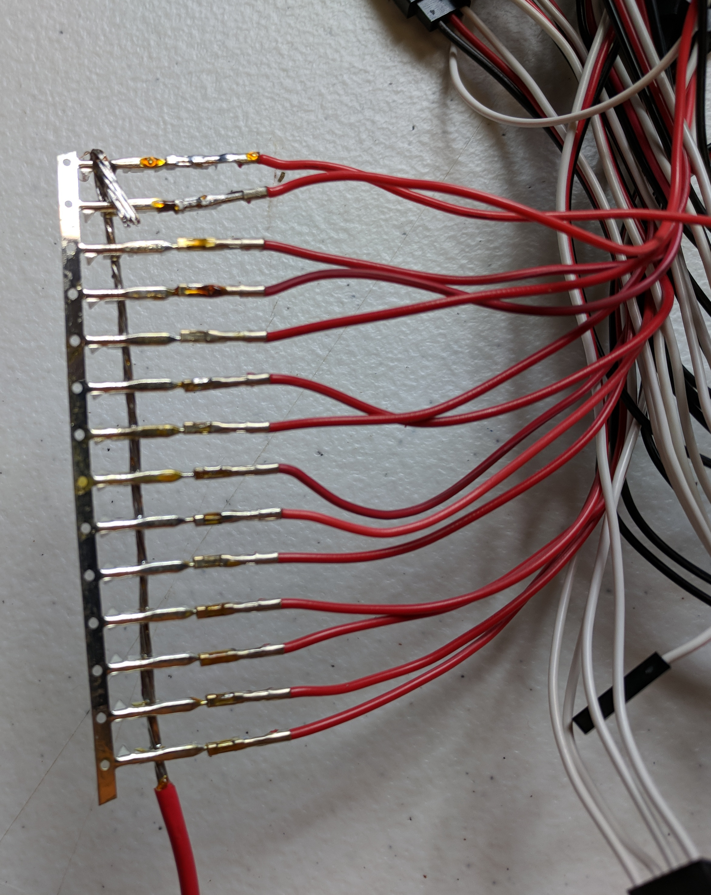
| 18:21, 26 September 2018 | Red-Servo-Power-Distro.jpg (file) |  |
1.79 MB | Vorpalwiki | 1 | |
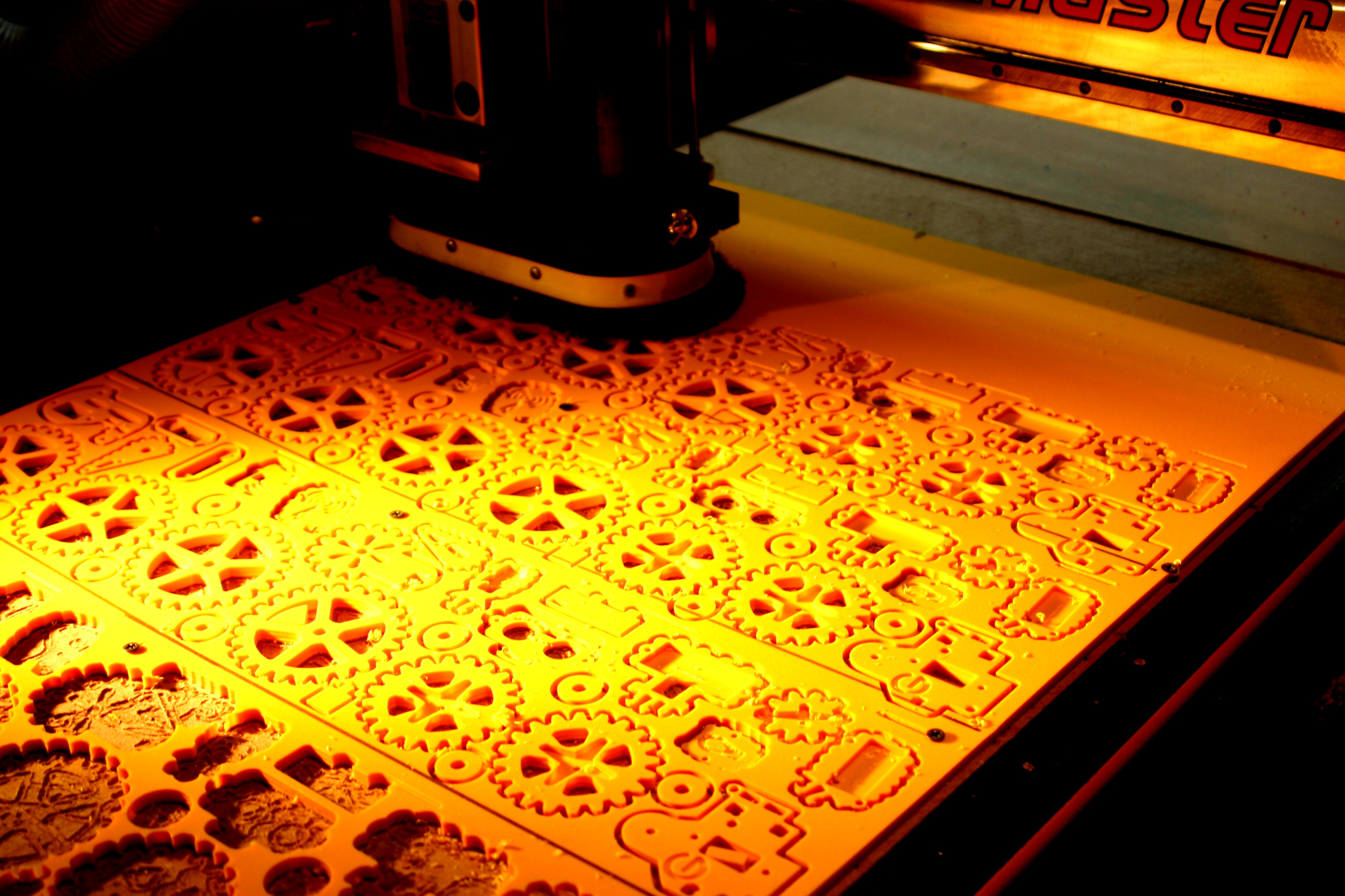
| 04:37, 10 July 2015 | Mimsy-CNC-Router-Gears.JPG (file) |  |
1.75 MB | Vorpalwiki | CNC router cutting Mimsy yellow parts in the Vorpal Robotics LLC workshop. | 1 |
| 23:25, 28 June 2015 | Mimsy-build-fig-08.jpg (file) |  |
1.75 MB | Vorpalwiki | Mimsy Build figure 8. It's easier to insert the 20-tooth gear with servo horn by holding the drive train with the servo on top. Slide the gear/horn in between the plates and using the large pie-shaped holes on the outer plate, position the gear/horn. Y... | 1 |
| 00:45, 20 October 2019 | NewSwitchInstall-Step3.jpg (file) |  |
1.67 MB | Vorpalwiki | 1 | |
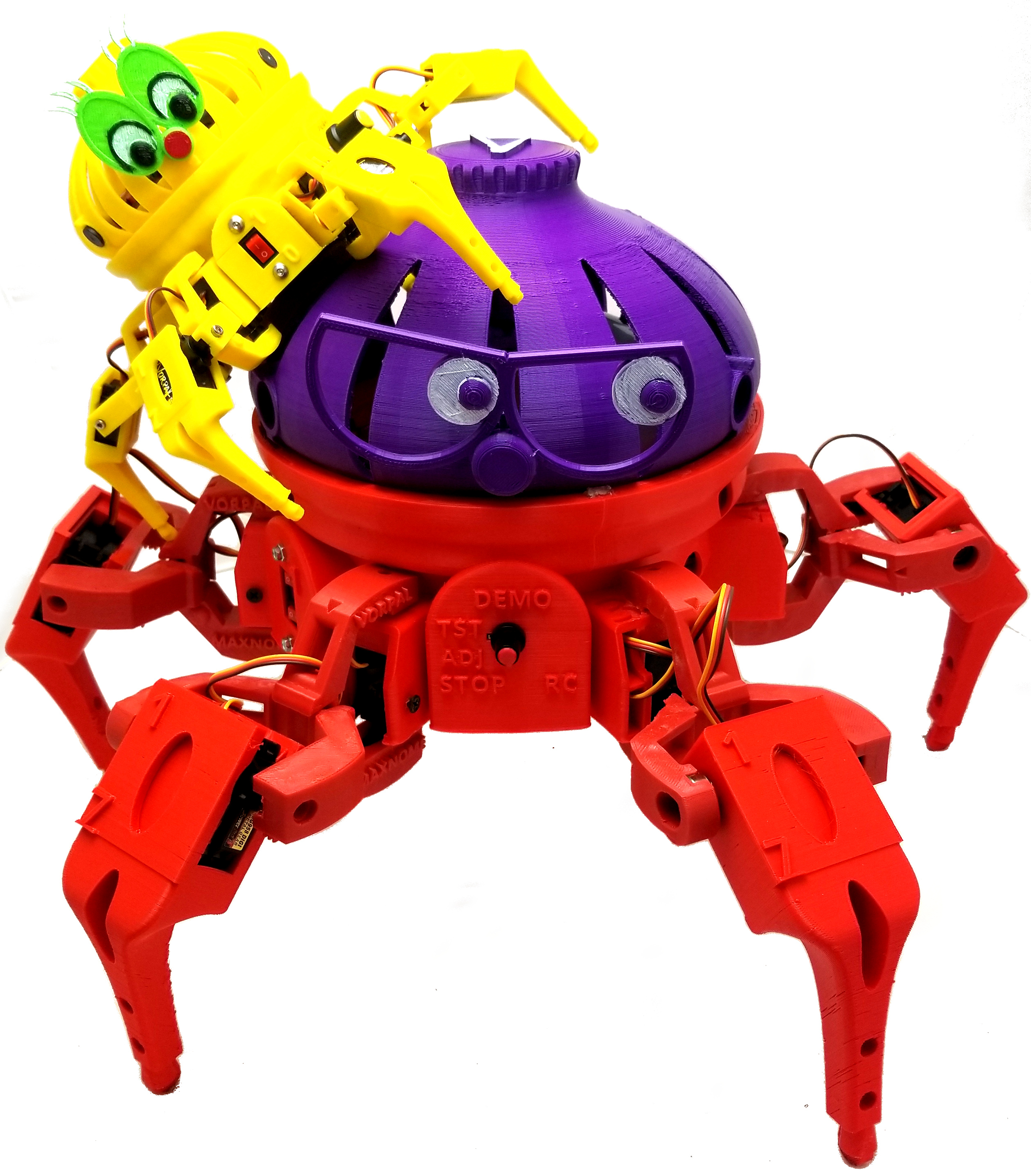
| 13:19, 28 September 2018 | Vorpal-Riding-Max-tilted.jpg (file) |  |
1.65 MB | Vorpalwiki | 1 | |
| 13:07, 19 January 2018 | Base-Bare-Purple-Lights.jpg (file) |  |
1.64 MB | Vorpalwiki | 1 | |
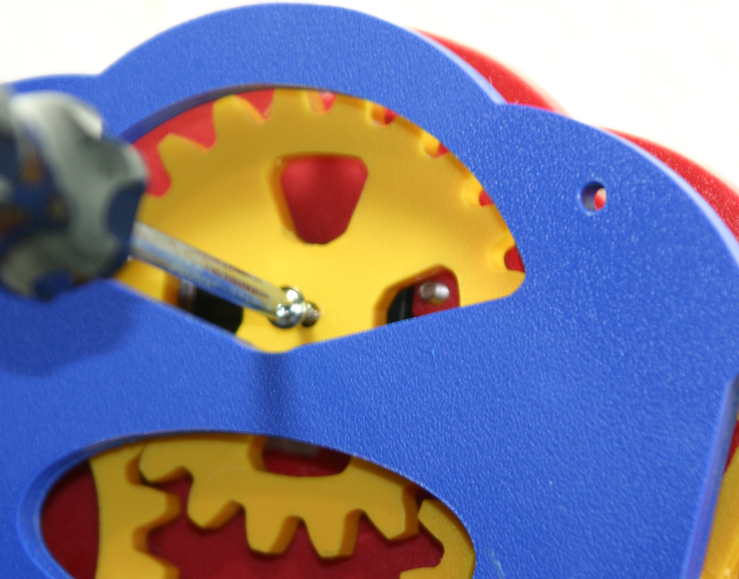
| 23:31, 28 June 2015 | Mimsy-build-fig-09.jpg (file) |  |
1.59 MB | Vorpalwiki | Mimsy Build figure 9. Secure the 20-tooth gear to the servo using a pointed screw. NOTE: do not use the tiny phillips head screwdriver that came with your kit, that's for adjusting the sound sensor and LCD backlight and it's not strong enough. | 1 |
| 16:59, 22 June 2015 | 01-mimsy-all-red-center.jpg (file) |  |
1.5 MB | Vorpalwiki | Vorpal Mimsy 1.1 with all red parts down the center of the robot. | 1 |
| 02:29, 30 June 2015 | Mimsy-build-fig-28.jpg (file) |  |
1.48 MB | Vorpalwiki | Mimsy Build figure 28. Route the cables as shown and use the console wire plate and two 3/8" screws to hold them in place. | 1 |
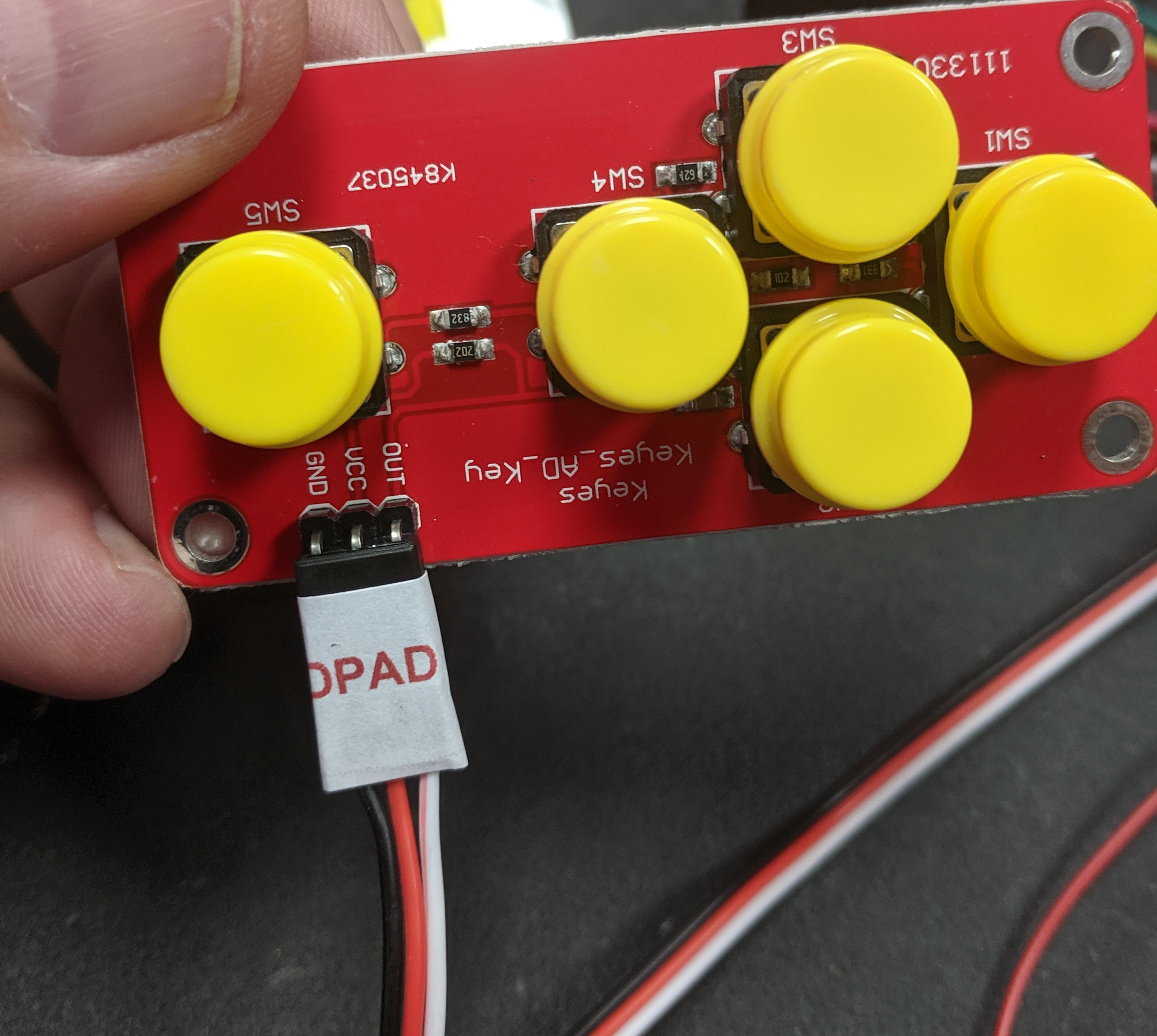
| 17:28, 22 October 2019 | DPAD-plug.JPG (file) |  |
1.47 MB | Vorpalwiki | 1 | |
| 00:45, 20 October 2019 | NewSwitchInstall-Step2.jpg (file) |  |
1.45 MB | Vorpalwiki | 1 | |
| 02:34, 30 June 2015 | Mimsy-build-fig-29.jpg (file) |  |
1.41 MB | Vorpalwiki | Mimsy Build figure 29. The console fits in the two slots on the rear of Mimsy as shown. | 1 |
| 17:44, 9 July 2015 | Mimsy-build-fig-33.jpg (file) |  |
1.39 MB | Vorpalwiki | Mimsy build figure 33. | 1 |
| 12:41, 19 January 2018 | VorpalVaseDazzlerElectronics.jpg (file) |  |
1.39 MB | Vorpalwiki | 1 | |
| 02:15, 30 June 2015 | Mimsy-build-fig-27.jpg (file) |  |
1.38 MB | Vorpalwiki | Mimsy Build figure 27. Install the buzzer using two 3/8" screws, do not overtighten. Connect the LCD cable as shown with the black wire at the top. | 1 |
| 02:28, 29 June 2015 | Mimsy-build-fig-21.jpg (file) |  |
1.37 MB | Vorpalwiki | Mimsy Build figure 21. The front floor is shown with fence installed. | 1 |
| 03:05, 29 June 2015 | Mimsy-build-fig-25.jpg (file) |  |
1.36 MB | Vorpalwiki | Mimsy Build figure 25. The LCD is secured with two screws at the top of the console bezel. | 1 |
| 02:42, 29 June 2015 | Mimsy-build-fig-22.jpg (file) |  |
1.33 MB | Vorpalwiki | Mimsy Build figure 22. Parts needed to assemble control panel. | 1 |
| 16:17, 1 April 2018 | Hexapod-electrical-system.jpg (file) |  |
1.32 MB | Vorpalwiki | 1 | |
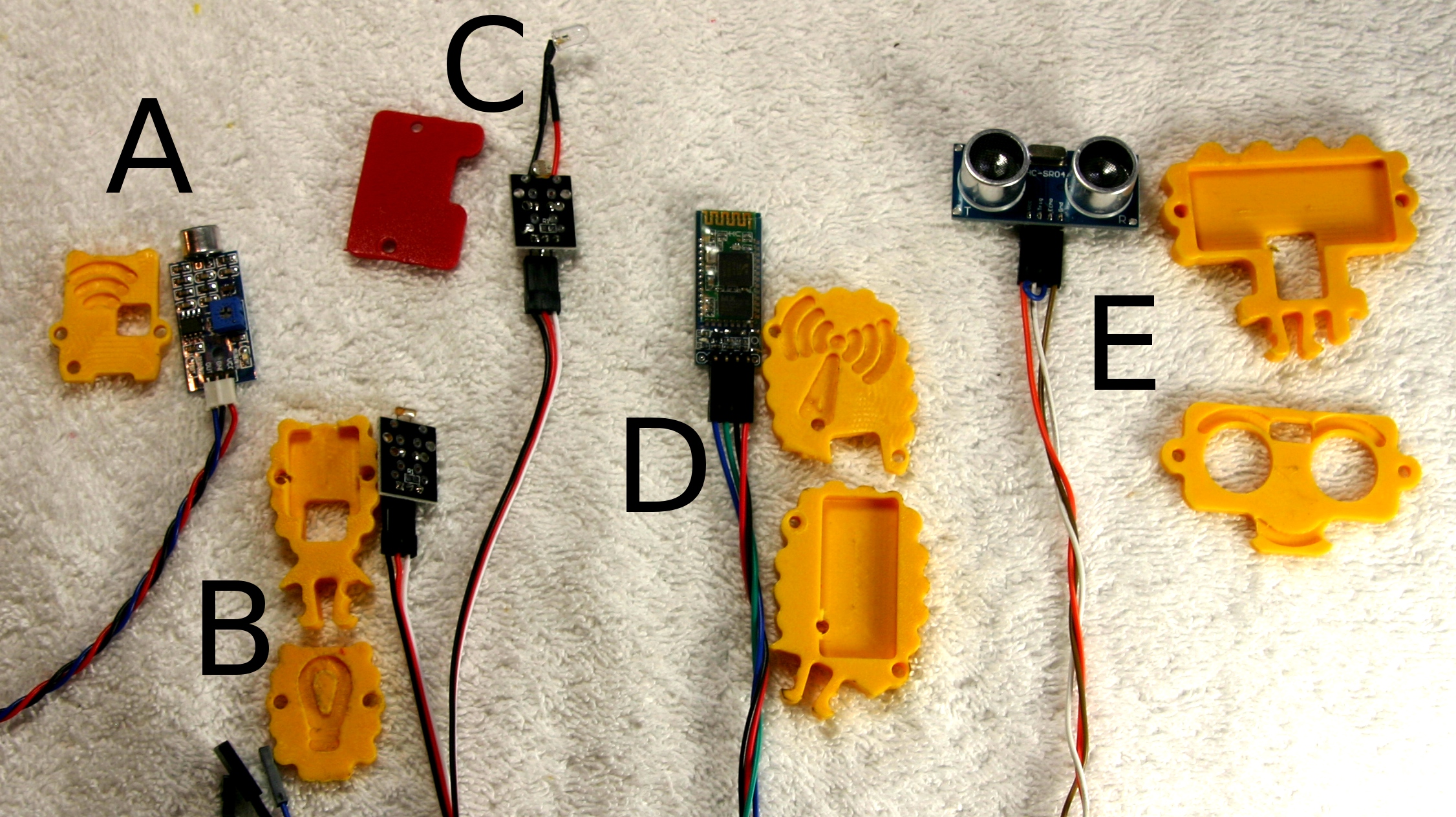
| 02:09, 24 June 2015 | Mimsy-annotated.jpg (file) |  |
1.32 MB | Vorpalwiki | Vorpal Mimsy sensors and actuator. | 1 |
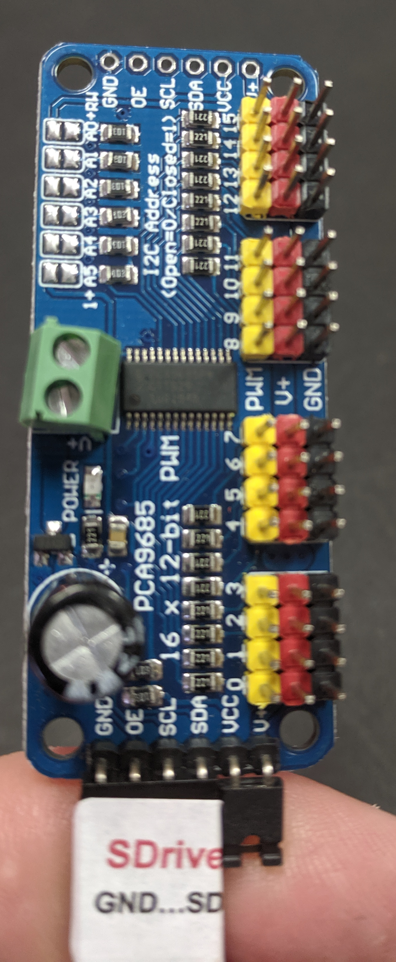
| 13:41, 22 October 2019 | SDriver-GND-SDA.JPG (file) |  |
1.31 MB | Vorpalwiki | 1 | |
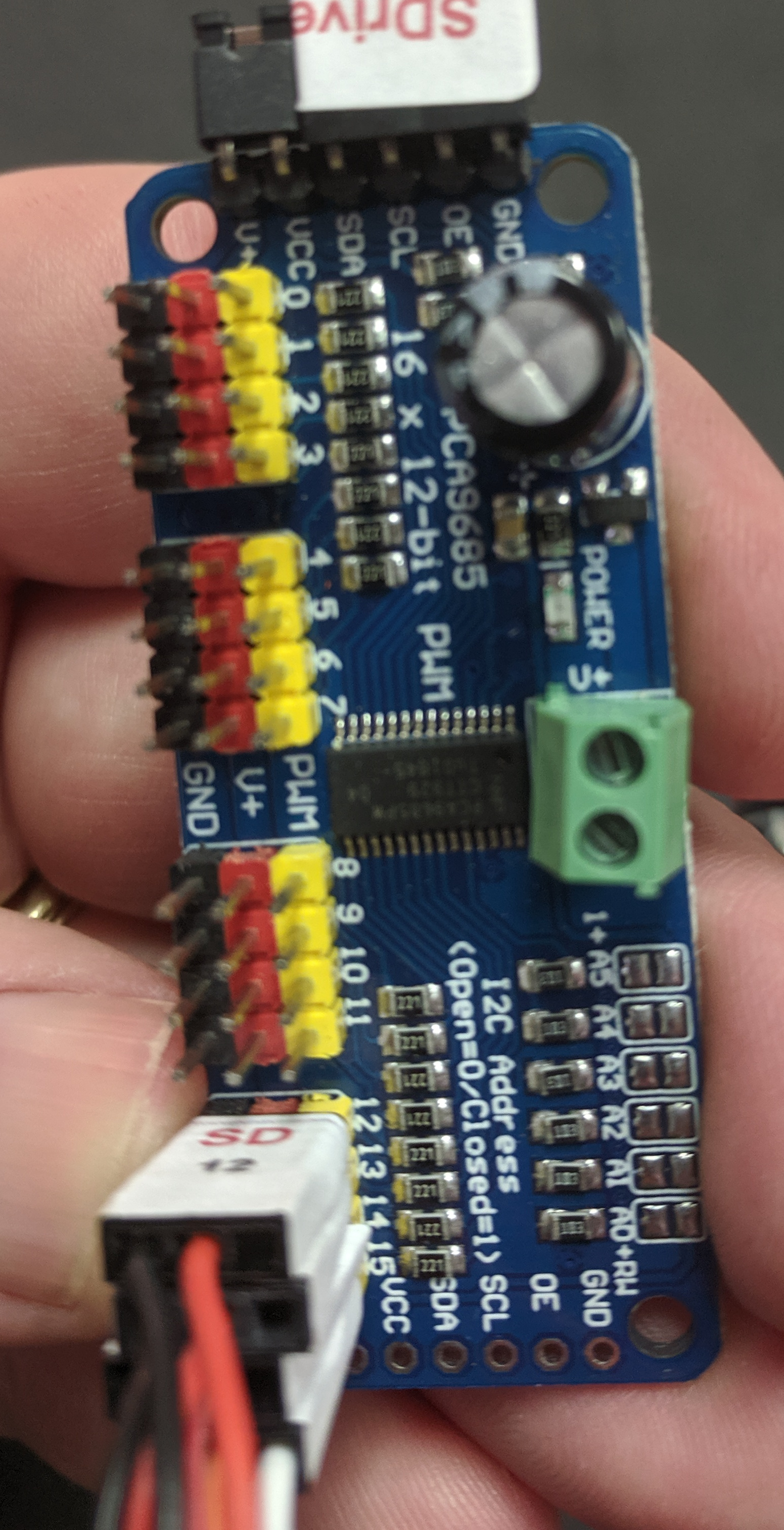
| 13:51, 22 October 2019 | SD12-to-SD15.JPG (file) |  |
1.29 MB | Vorpalwiki | 1 | |
| 01:51, 29 June 2015 | Mimsy-build-fig-18.jpg (file) |  |
1.27 MB | Vorpalwiki | Mimsy Build figure 18. Front view of chassis with servo wires routed to the rear. | 1 |
| 18:31, 1 July 2017 | Scamp-Leg-Raised.jpg (file) |  |
1.25 MB | Vorpalwiki | 1 | |
| 17:46, 9 July 2015 | Mimsy-build-fig-34.jpg (file) |  |
1.22 MB | Vorpalwiki | Mimsy build figure 34. | 1 |
| 18:31, 9 July 2015 | Mimsy-build-fig-36.jpg (file) |  |
1.2 MB | Vorpalwiki | Mimsy build figure 36. | 1 |
| 23:35, 28 June 2015 | Mimsy-build-fig-10.jpg (file) |  |
1.2 MB | Vorpalwiki | Mimsy Build figure 10. The two drive trains are now ready to be connected together. | 1 |
| 17:47, 9 July 2015 | Mimsy-build-fig-35.jpg (file) |  |
1.15 MB | Vorpalwiki | Mimsy build figure 35. | 1 |
| 11:16, 16 September 2017 | VCH-Scamp-Leg-Raised.jpg (file) |  |
1.12 MB | Vorpalwiki | 1 | |
| 01:44, 29 June 2015 | Mimsy-build-fig-17.jpg (file) |  |
1.09 MB | Vorpalwiki | Mimsy Build figure 17: using the same locking tab and slot system, take the sensor bar and align and press in first one side and then the other. | 1 |
| 01:10, 29 June 2015 | Mimsy-build-fig-14.jpg (file) |  |
1.08 MB | Vorpalwiki | Mimsy Build figure 14. Front and rear floors installed on one drive train. | 1 |
| 14:05, 22 October 2019 | GNANO-D13-VIN.JPG (file) |  |
1.06 MB | Vorpalwiki | 1 | |
| 17:45, 22 October 2019 | GNANO-GND-D12v2.JPG (file) |  |
1.03 MB | Vorpalwiki | 1 | |
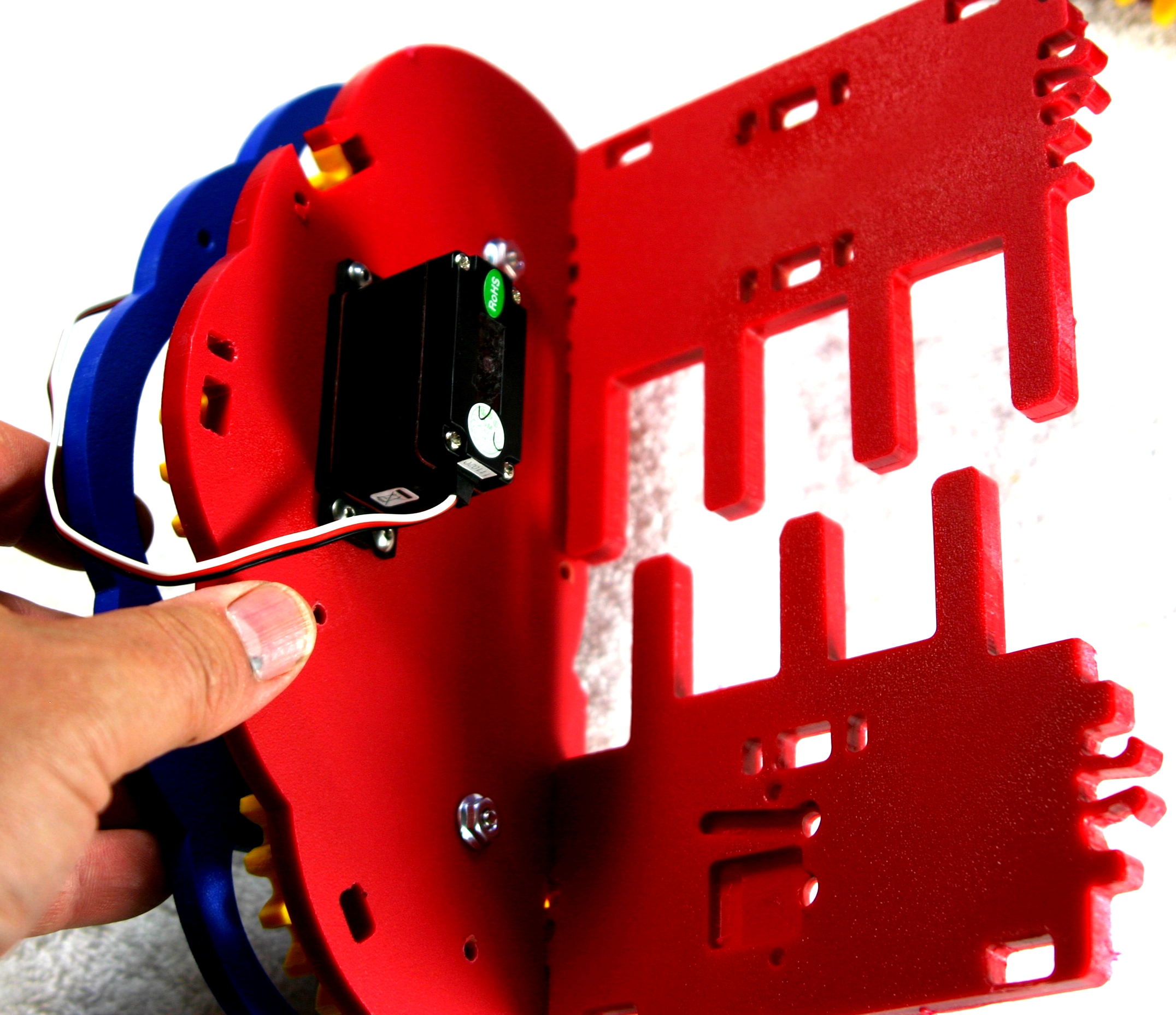
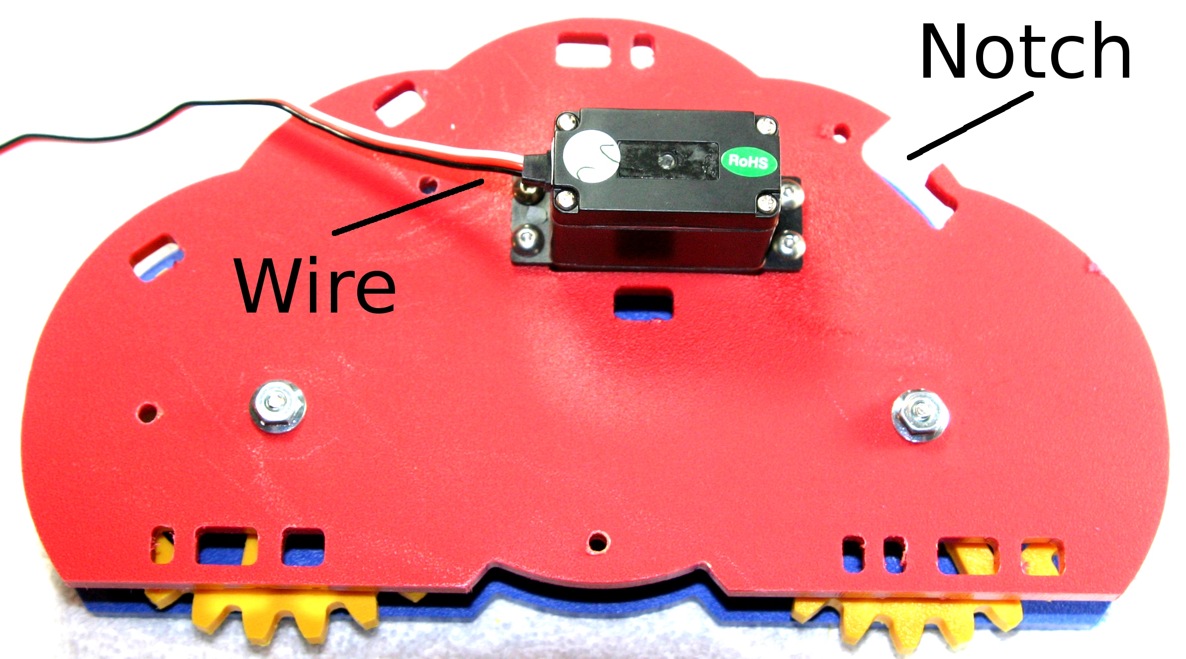
| 21:40, 28 June 2015 | Mimsy-build-fig-06.jpg (file) |  |
1.02 MB | Vorpalwiki | Mimsy build figure 6. Make sure the servo motor's wire is on the opposite side from the notch in the inner plate. | 1 |
| 17:39, 22 October 2019 | MATRIX-1-8v2.jpg (file) |  |
1 MB | Vorpalwiki | 1 | |
| 18:57, 9 July 2015 | Mimsy-build-fig-39.jpg (file) |  |
984 KB | Vorpalwiki | Mimsy build figure 39. | 1 |
| 01:31, 29 June 2015 | Mimsy-build-fig-15.jpg (file) |  |
981 KB | Vorpalwiki | Mimsy Build figure 15. Insert the cross bar with the two square holes facing the side of the servos that have the wires. You need to angle it in. Just loosely put both sides in the slots, don't force it forward to lock yet. | 1 |