Difference between revisions of "Vorpal The Hexapod Battery/Switch Construction"
From Vorpal Robotics Wiki
Vorpalwiki (talk | contribs) |
Vorpalwiki (talk | contribs) (→Gamepad Battery/Switch Assembly) |
||
| Line 1: | Line 1: | ||
= Gamepad Battery/Switch Assembly = | = Gamepad Battery/Switch Assembly = | ||
| + | Note: If you purchase kit parts from Vorpal Robotics, you will receive the battery/switch assemblies for both the hexapod and gamepad pre-assembled with no soldering required. These instructions are for people who wish to source their own parts. These instructions assume you are familiar with soldering, stripping wires, and other basic electrical tasks. | ||
| + | |||
| + | You will need: | ||
| + | * A standard 9v battery clip with RED/BLACK color coded lead wires. | ||
| + | * A rocker switch, single throw single pole. The hole for the switch in the 3D models is 10mm x 14mm. If you can't get that exact size you either have to keep the switch inside the robot and remove the cap to use it, or you would need to modify the 3D models. | ||
| + | * Two single pin Dupont female connectors, preferably one RED and one BLACK wire so you can color code the power properly. | ||
| + | * Some shrink tube or electrical tape to insulate connections. | ||
| + | * Tools and supplies: wire stripper, soldering iron, solder, heat gun or other means to shrink the shrink tube. | ||
| + | |||
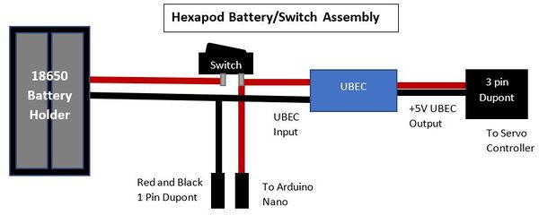
| + | The diagram below shows how connections are made. As usual, RED colored wires will be connected to positive voltage, while BLACK wires are for ground. | ||
| + | |||
[[FILE:Gamepad-Electrical-Switch-Assembly.jpg|600px]] | [[FILE:Gamepad-Electrical-Switch-Assembly.jpg|600px]] | ||
Revision as of 18:56, 25 July 2017
Gamepad Battery/Switch Assembly
Note: If you purchase kit parts from Vorpal Robotics, you will receive the battery/switch assemblies for both the hexapod and gamepad pre-assembled with no soldering required. These instructions are for people who wish to source their own parts. These instructions assume you are familiar with soldering, stripping wires, and other basic electrical tasks.
You will need:
- A standard 9v battery clip with RED/BLACK color coded lead wires.
- A rocker switch, single throw single pole. The hole for the switch in the 3D models is 10mm x 14mm. If you can't get that exact size you either have to keep the switch inside the robot and remove the cap to use it, or you would need to modify the 3D models.
- Two single pin Dupont female connectors, preferably one RED and one BLACK wire so you can color code the power properly.
- Some shrink tube or electrical tape to insulate connections.
- Tools and supplies: wire stripper, soldering iron, solder, heat gun or other means to shrink the shrink tube.
The diagram below shows how connections are made. As usual, RED colored wires will be connected to positive voltage, while BLACK wires are for ground.

